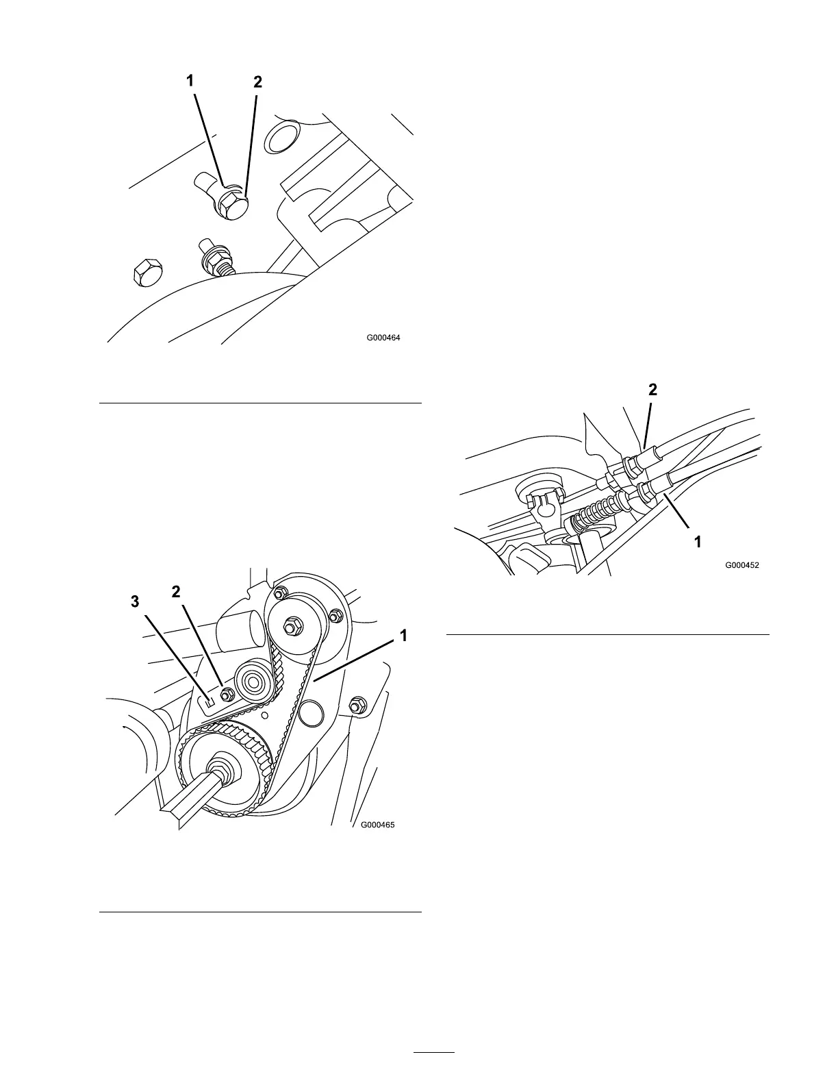
Figure 42
1. Tang washer 2. Idler bracket bolt
B . Using a 3/8 inc h dri v e tor que wrenc h,
rotate the idler brac k et with 35-40 in.-lb . of
tor que to set the belt tension ( Figure 43 ).
W hile holding the tor que wrenc h setting,
tighten the idler brac k et mounting bolt
(T he tang w asher is installed to prev ent the
belt from slipping .). Do not o v er -tension
the belt.
Figure 43
1. Traction drive belt 3. 3/8 inch Torque wrench
here
2. Idler bracket
C . Install the belt co v er .
Controls System
Maintenance
Adjusting the Traction
Control
If traction control does not eng ag e or it slips
during operation, an adjustment is required.
1. Mo v e traction control to Diseng ag ed position.
2. T o increase cable tension, loosen front cable
jam n ut and tighten bac k cable jam n ut
( Figure 44 ) until a force of 12-16 lb . is required
to eng ag e traction control.
Measure the force at the control knob .
Figure 44
1. Traction cable 2. Service/parking brake cable
3. Tighten front cable jam n ut.
4. Chec k control operation.
Adjusting the Reel Control
If reel control does not eng ag e or it slips during
operation, an adjustment is required.
1. Mak e sure traction control is properly adjusted;
refer to Adjusting the T raction Control.
2. T o increase cable tension, loosen front cable
jam n ut and tighten bac k cable jam n ut
( Figure 45 ) (located on top of g ear bo x)
until the reel cable force adds 7 to 10 lbs . of
additional handle force measured at the control
knob .
Note: If traction control handle force is
12 lbs ., the combined traction and reel force
should be 19 to 22 lbs .
31
 Loading...


