Figure 49
1. Spacer
3. Roller bracket
2. Sideplate mounting ange
• P osition the spacer belo w the side plate
mounting flang e when height of cut
settings rang e from 1/8" to 1" ( Figure 50 ).
Figure 50
1. Sideplate mounting ange 3. Roller bracket
2. Spacer
2. T o adjust rear roller proceed as follo ws:
• Raise rear of cutting unit and place a bloc k
under bedknife .
• R emo v e (2) n uts securing eac h roller
brac k et and spacer to eac h side plate
mounting flang e .
• Lo w er roller and screws from side plate
mounting flang es and spacers .
• Place spacers onto screws on roller
brac k ets .
• R e-secure roller brac k et and spacers to
underside of side plate mounting flang es
with n uts previously remo v ed.
3. V erify that the bedknife to reel contact is
cor rect. Tip mo w er to expose front and rear
rollers and bedknife .
Note: T he position of the rear roller to the
reel is controlled b y the mac hining tolerances
of the assembled components and paralleling is
not required. A limited amount of adjustment
is possible b y setting the cutting unit on a
surface plate and loosening the side plate
mounting bolts ( Figure 51 ). Adjust and
re-tighten bolts .
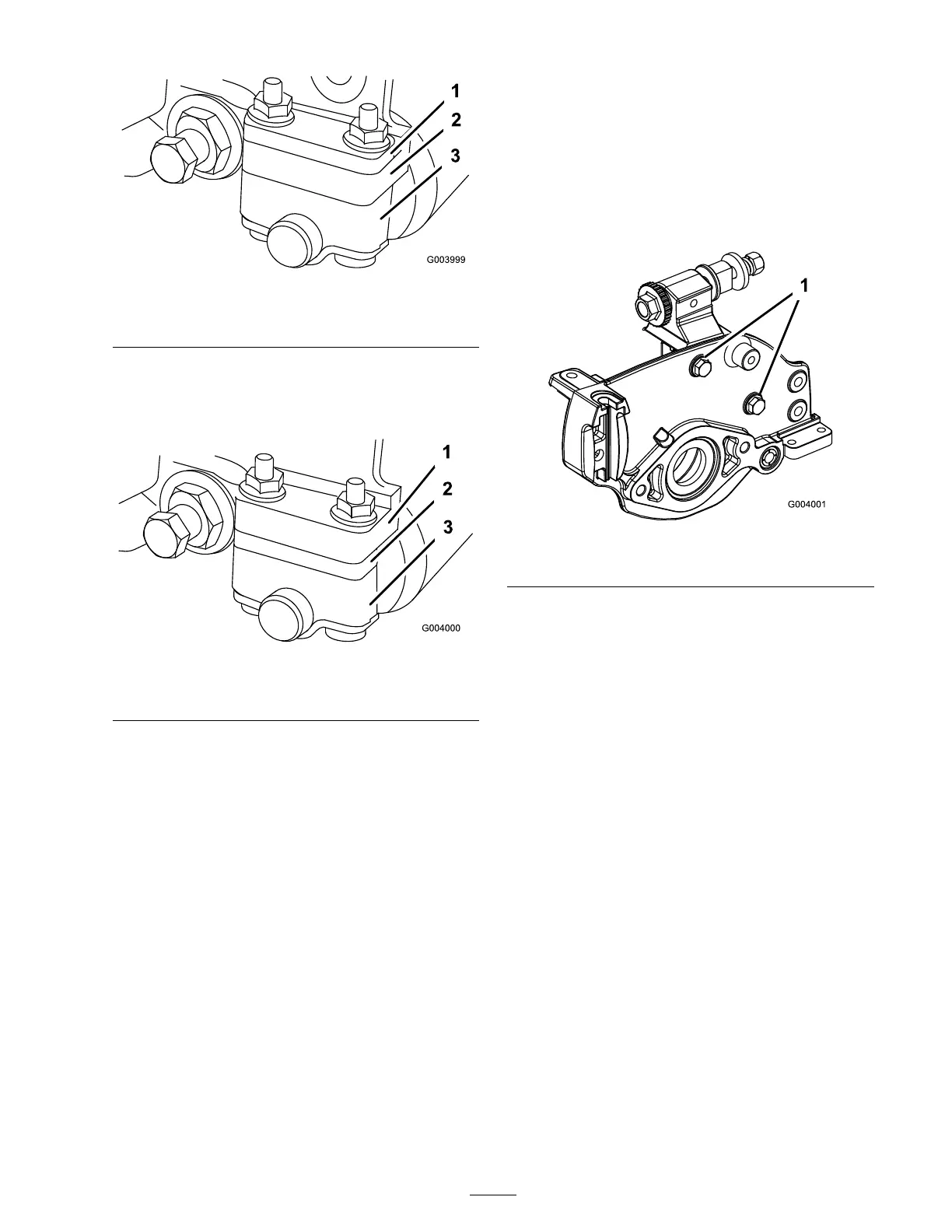
Figure 51
1. Sideplate mounting bolts
Important: W henev er the cutting unit
has to be tipped to expose bedknife/r eel,
pr op up r ear of cutting unit to mak e sur e
n uts on back end of bedbar adjusting
scr ews ar e not r esting on w or k surf ace.
Adjusting the Bedknife to
the Reel
Bedknife to reel adjustment is accomplished b y
loosening or tightening bedbar adjusting screws ,
located on top of mo w er .
1. P osition mac hine on a flat, lev el w ork surface .
2. Mak e sure reel contact is remo v ed b y tur ning
bedbar adjusting screws countercloc kwise
( Figure 52 ).
33
 Loading...


