Use the follo wing table and Figure 58 to set the
rate of clip .
Clip (Refer to Figure 58 for pulley locations.)
Drive pulley number of
teeth
Driven pulley number
of teeth
11 Blade Clip 8 Blade Clip
27 22
.14 inches (standard)
.19 inches
22 22
.16 inches .24 inches
22 27
.21 inches .29 inches
T he reel is shipped with one 27 tooth and one
22 tooth pulley . T o g et a .16 inc h clip , y ou m ust
purc hase a 22 tooth pulley . T he clip can only be
c hang ed on the reel dri v e ( Figure 58 ). Do not
c hang e the dri v e ratio on the g earbo x pulleys .
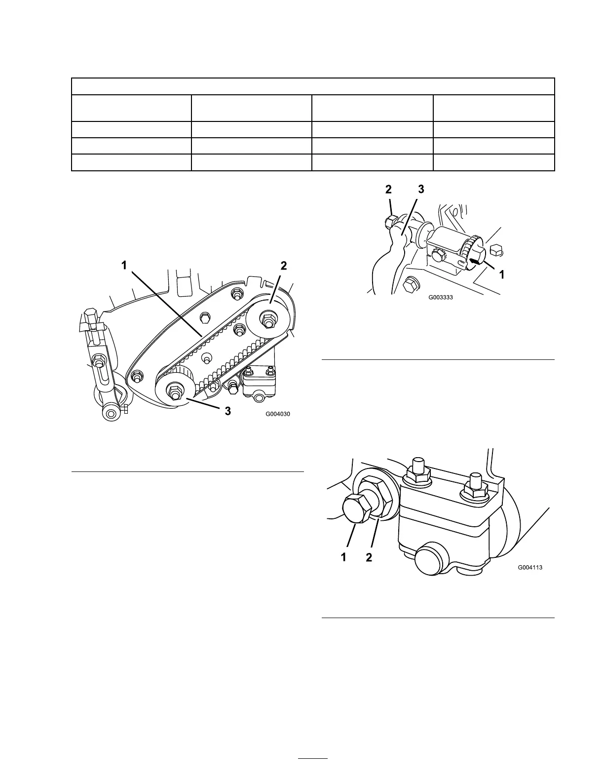
Figure 58
1. Reel drive belt 3. Driven pulley
2. Drive pulley
Servicing the Bedbar
Removing the Bedbar
1. T ur n the bedbar adjuster screw ,
countercloc kwise , to bac k the bedknife
a w a y from reel ( Figure 59 ).
Figure 59
1. Bedbar adjusting screw
4. Jam nut
2. Spring tension nut
5. Bedbar bolt
3. Bedbar
2. Bac k out the spring tension n ut, until the
w asher is no long er tensioned ag ainst the
bedbar ( Figure 60 ).
3. On eac h side of the mac hine , loosen the jam
n ut securing the bedbar bolt ( Figure 60 ).
Figure 60
1. Bedbar bolt
2. Nut
4. R emo v e eac h bedbar bolt allo wing bedbar to be
pulled do wnw ard and remo v ed from mac hine .
Account for 2 nylon and 2 stamped steel
w ashers on eac h end of bedbar ( Figure 61 ).
37
 Loading...


