ElectricalSystem
Maintenance
Servicingthe
Traction-InterlockSwitch
Usethefollowingprocedureifthetraction-interlock
switchneedsadjustmentorreplacement.
1.Ensurethattheengineisoff.
2.Removethecontrolpanel.
3.Engagethetractionlever.
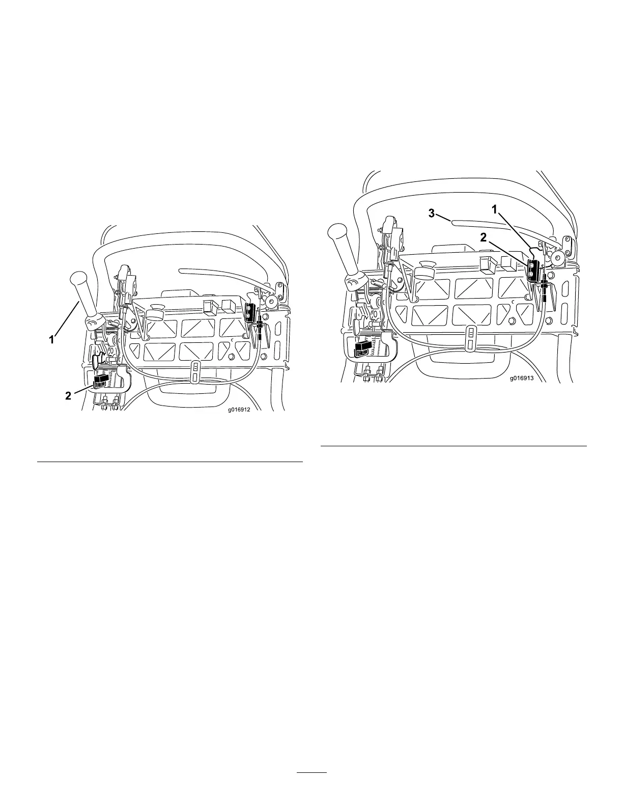
g016912
Figure40
1.Tractionlever2.Interlockswitch
4.Loosentheinterlockswitchmountingfasteners
(Figure40).
5.Placea1.6mm(0.062inch)thickshimbetween
thetractionleverandtheinterlockswitch(Figure
40).
6.Tightentheinterlockswitchmountingfasteners.
7.Engagethetractionleverandcheckthegap.
Thenormaloperatingrangeisbetween0.76to
3.05mm(0.03to0.12inch).Withthetraction
leverengaged,verifythattheswitchloses
continuity.Replacetheswitchifnecessary.
Servicingthe
Brake-InterlockSwitch
1.Ensurethattheengineisoff.
2.Removethecontrolpanel.
3.Engagetheservice-brakeleverandengagethe
parking-brakelatch.
4.Loosenandremovetheinterlock-switch
mountingfasteners(Figure41).
g016913
Figure41
1.Parking-brakelatch
3.Service-brakelever
2.Interlockswitch
5.Placea1.6mm(0.062inch)thickshimbetween
theparking-brakelatchandtheinterlockswitch
(Figure41).
6.Installandtightentheinterlockswitchmounting
fasteners.Checkthegap.Thelatchmustnot
contacttheswitch.
7.Engagethebrakeleverandrotatethelatch.
Verifythattheswitchlosescontinuity.Replace
theswitchifnecessary.
34

 Loading...


