g000483
Figure6
1.Transmissioncoupling
4.Maneuverthemachineframeforwarduntilit
engagesthecuttingunitpivotarmsFigure7.
g032418
Figure7
1.Telescopingcoupler3.Bolt
2.Cutting-unithexshaft
5.Securethemachineframetothecuttingunit
pivotarmswiththe2bolts(3/8x3/4inch)
(Figure7).
6.MovethekickstandtotheSTORAGEposition
byreleasingthelockingpinandallowingthe
kickstandtorotateup.
7.Setthecutting-unitheightofcut;refertoyour
cuttingunitOperator’sManual.
3
InstallingtheHandle
Retainers
Partsneededforthisprocedure:
2Handleretainer
2Hairpincotter
Procedure
1.Whilesupportingthehandle,removethecable
tiesthatsecurethehandleclampstotheside
plates(Figure8).
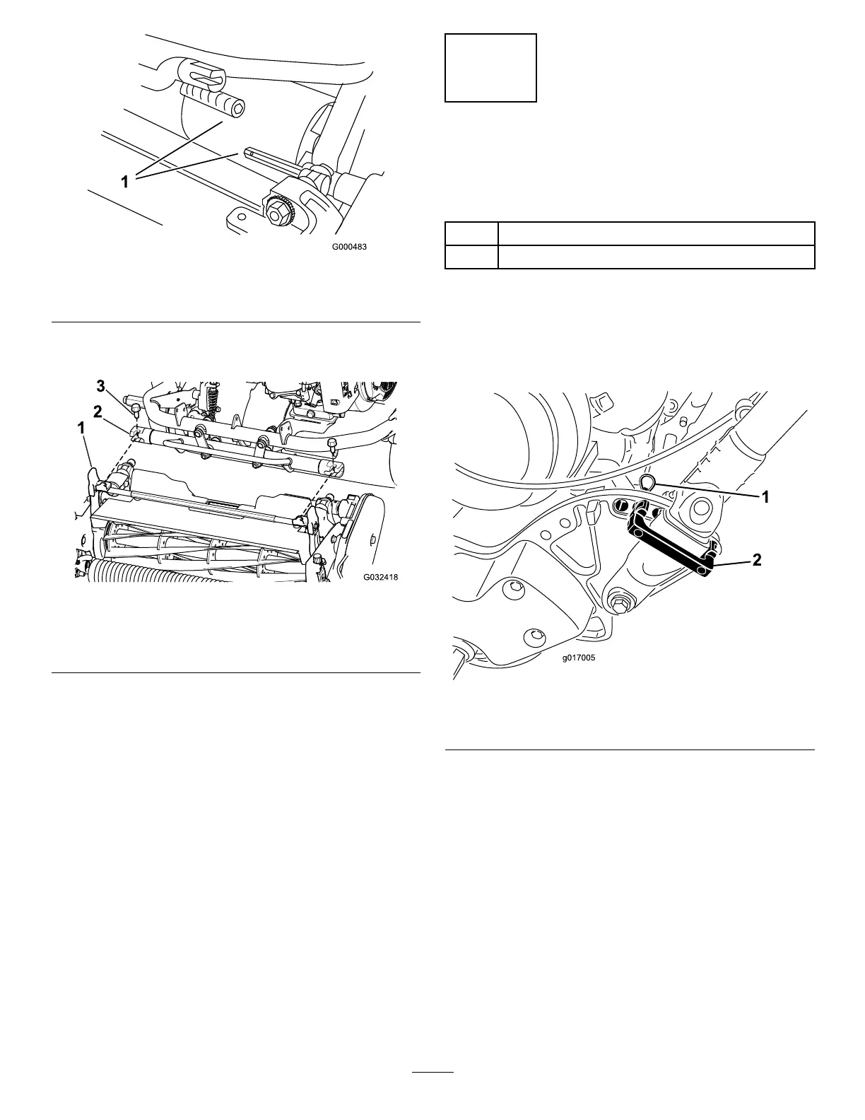
g017005
Figure8
1.Hairpincotter2.Handleretainer
2.Pivotthehandletothedesiredoperatingposition
andinsertahandleretaineroverthehandle
clampandintothematchingholesintheside
plate(Figure8).
3.Securetheclampinpositionwithahairpincotter
(Figure8).
4.Repeattheprocedureontheoppositesideof
thehandle.
5.Adjustthehandleheighttothedesiredposition;
refertoAdjustingtheHandleHeight(page20).
Note:Themachineisshippedwiththehandle
adjustedtothelowestposition.Themachineis
traditionallyoperatedwiththehandletelescoped
outtoitsmaximumheight.
9

 Loading...


