ControlsSystem
Maintenance
AddingFluidtotheClutch
Assembly
Fluidspecication:ATFD/MAutomatic
TransmissionFluid(T oroPartNo.505-136)
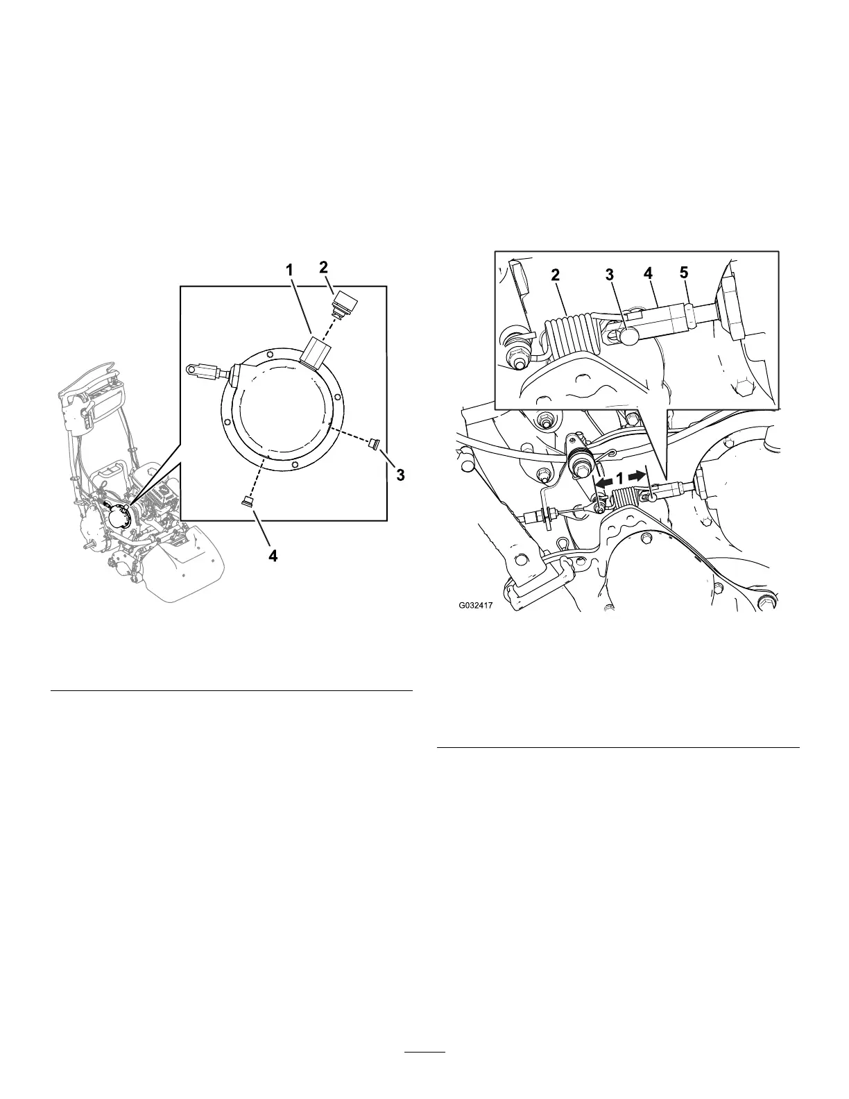
1.Removetheventfromthebreatherfromthe
transmissionassembly(Figure47).
g295805
Figure47
1.Breather3.Levelplug
2.Vent4.Drainplu
2.Removethedrainplug(Figure47)andallowthe
transmissionuidtodrainfromthetransmission
housing.
3.Addthespecieduid(296mlor10oz)
throughthebreatheropening.
4.Applyalightcoatingofcleanmotoroil(SAE30)
ontotherubberportionofthesealsandO-rings
(breatherandlevelplug)priortoassembly.
5.Installdrainplugtotheclutchassemblyand
torqueitto14N∙m(10ft-lbs).
6.Removethelevelplug(Figure47)toconrm
uidlllevel.
7.Installthelevelplugandtorqueitto14N∙m(10
ft-lbs).
8.Installtheventtothebreather.Tightenuntil
gasketcontactsandthentightenanadditional
80°.
AdjustingtheTraction
Control
Ifthetractioncontroldoesnotengageorifitslips
duringoperation,anadjustmentisnecessary.
1.MovethetractioncontroltotheENGAGED
position.
2.Measurethedistancefromthepinoneither
endofthetraction-controlspring(Figure48);if
itisnotwithin7.3to7.6cm(2-7/8to3inches),
adjusttheclutchaccordingtothestepsbelow.
g032417
Figure48
1.Measurethisdistance
(shouldbe7.3to7.6cm
(2-7/8to3inches).
4.Turnbuckle
2.Traction-controlspring5.Jamnut
3.Clevispin
A.Disengagethetraction-controllever.
B.Loosenthejamnutontheturnbuckleand
removetheclevispin,disconnectingthe
springfromtheturnbuckle(Figure48).
C.Turntheturnbuckleinorouttoadjustthe
lengthasnecessary.
D.Installtheturnbuckletothespringwiththe
clevispin.
E.MovethetractioncontroltotheENGAGED
position.
F.Measurethedistancefromthepinoneither
endofthetraction-controlspring(Figure
48);repeatstepsAthroughFuntilitis
within7.3to7.6cm(2-7/8to3inches).
37

 Loading...


