g017948
Figure7
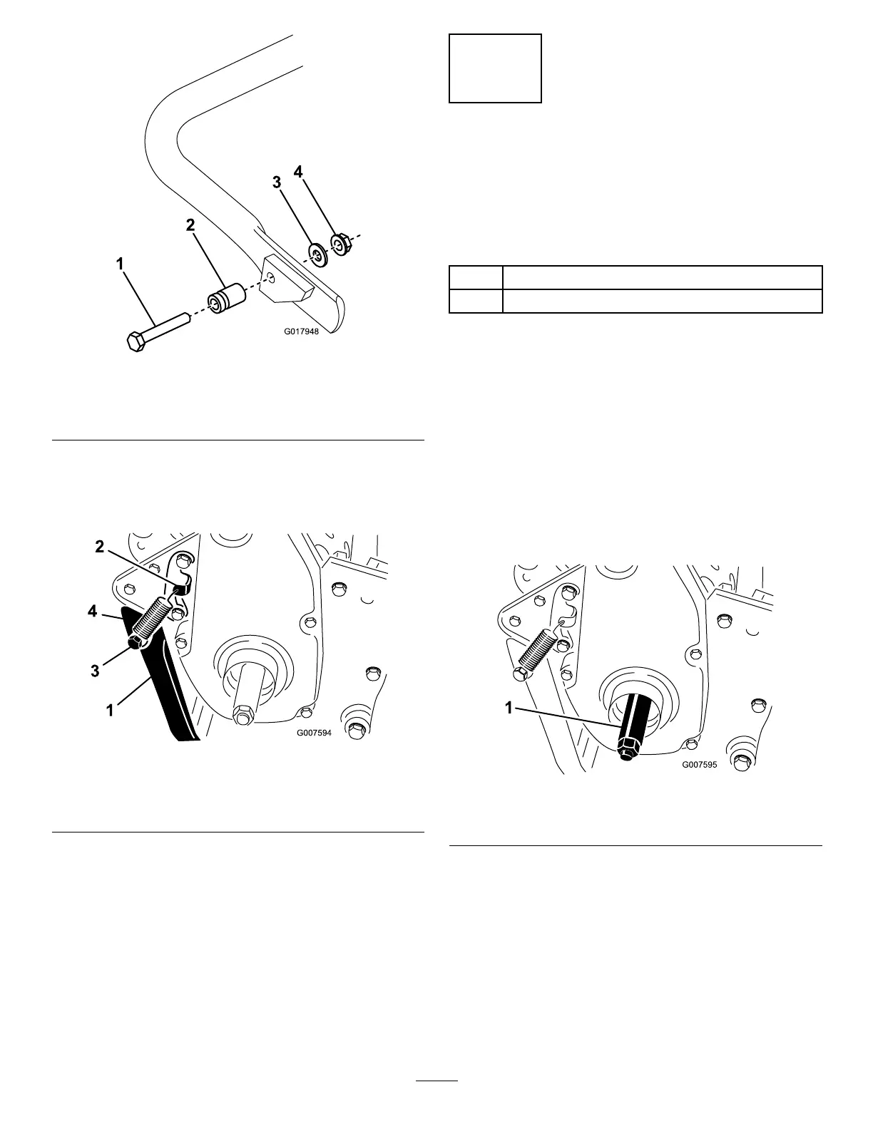
1.Bolt3.Washer
2.Springstud
4.Flange–headnut
2.Hookthespringintotheholeinthespring
bracketandontothespringstudwhilealigning
thekickstandwiththemountingholesintherear
frame(Figure8).
g007594
Figure8
1.Kickstand
3.Springstud
2.Springbracket4.Spring
3.Mountthekickstandtoeachsideoftheframe
withabolt,lockwasher,spacer,atwasher,and
locknut(Figure8).
4.Positionthespacerinthekickstandmounting
hole.
3
InstallingtheTransport
WheelShafts
Models04055and04056Only
Partsneededforthisprocedure:
1
Rightwheelshaft
1
Leftwheelshaft
Procedure
1.Pushthekickstanddownwithyourfootandpull
uponthehandletosupportthemachineonthe
kickstand.
2.Applythread-lockingadhesivetothethreadsof
thewheelshafts.
3.Threadtherightwheelshaftintothedrivepulley
ontherightsideofthemachine(Figure9).
Note:Therightwheelshafthasleft-hand
threads.
g007595
Figure9
1.Rightwheelshaft
4.Torquetheshaftto88to101N∙m(65to75ft-lb).
5.Repeatsteps2through4toinstalltheleftwheel
shafttotheleftsideofthemachine.
10

 Loading...


