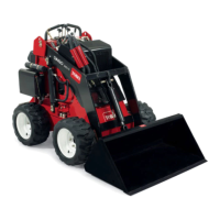
ProductOverview
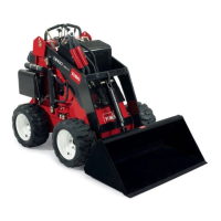
G005939
1
2
3
4
5
20
17
6
18
7
8
13
14
15
12
11
21
9
18
16
4
14
19
10
22
Figure6
1.Mountplate7.Wheel
13.Controlpanel
19.Parkingbrakelever
2.Tiltcylinder
8.Liftcylinder14.Liftpoints20.Radiatorllcap
3.Auxiliaryhydrauliccouplers
9.Operatorplatform
(removablecounterweight
notshown)
15.Handle21.Thighsupport
4.Loaderarms
10.Rearaccesscover(open)
16.Battery22.Flowdividercontrol
5.Frontaccesscover11.Engine17.Indicatorlights
6.Fueltank
12.Airlter
18.Towvalves
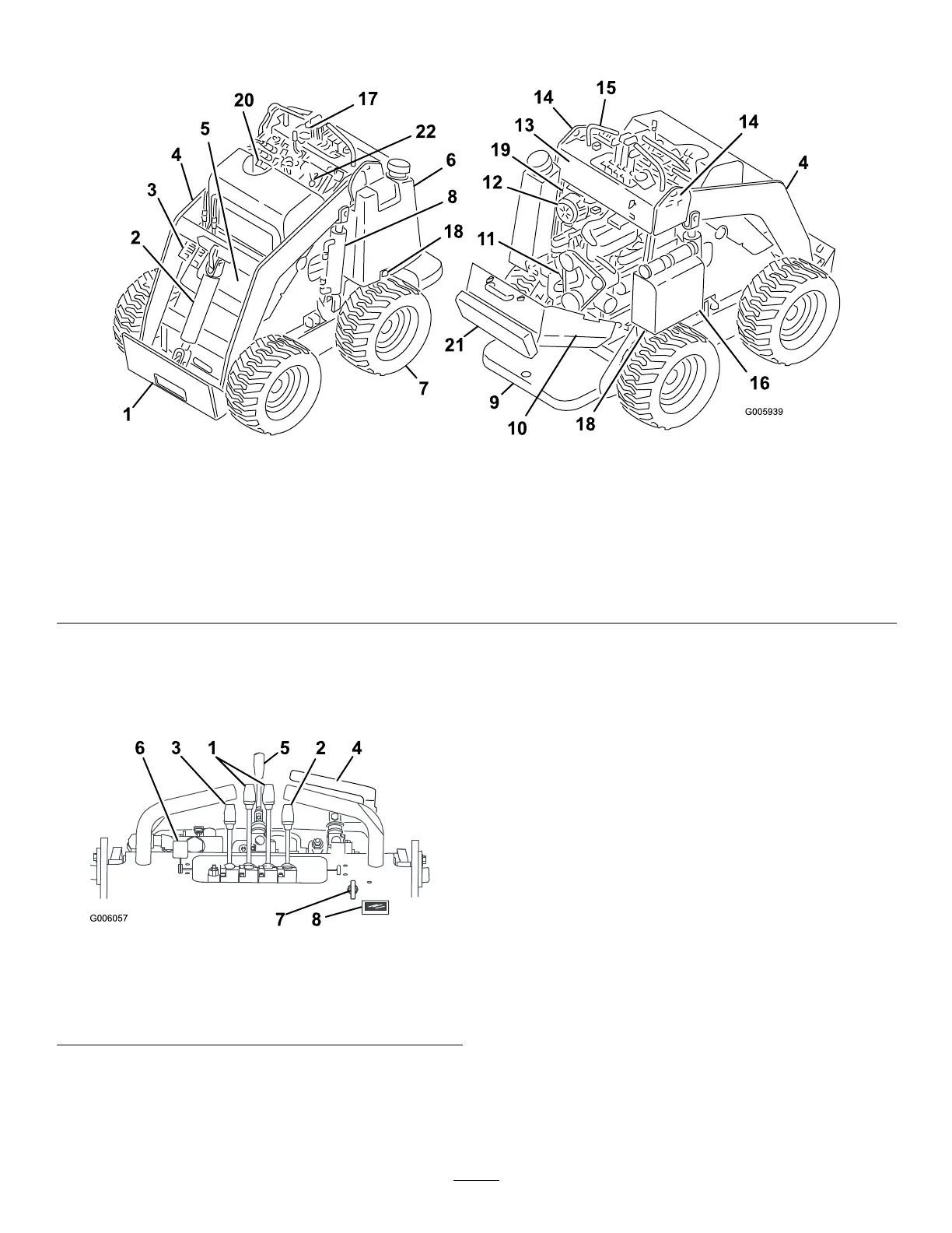
Controls
Becomefamiliarwithallthecontrols(Figure7)before
youstarttheengineandoperatethetractionunit.
G006057
631524
78
Figure7
1.Tractioncontrollevers
5.Speedselectorlever
2.Attachmenttiltlever6.Throttlelever
3.Loaderarmlever7.Keyswitch
4.Auxiliaryhydraulicslever8.Hourmeter
KeySwitch
Thekeyswitch,usedtostartandstoptheengine,has
threepositions:off,run,andstart.
•Tostarttheengine,rotatethekeytotherunposition,
theglowpluglightwillcomeon.Whentheglow
pluglightturnsoff,turnthekeytothestartposition.
Releasethekeywhenenginestartsanditwillmove
automaticallytotherunposition.
•Tostoptheengine,rotatethekeytotheoffposition.
ThrottleLever
Movethecontrolforwardtoincreasetheenginespeed
andrearwardtodecreasespeed.
TractionControlLevers
•Tomoveforward,movethetractioncontrollevers
forward.Tomoverearward,movethetraction
controlleversrearward.
•Togostraight,movebothtractioncontrollevers
equally.
•Toturn,movetheleverlocatedonthesideyou
wanttoturnbacktowardtheneutralpositionwhile
keepingtheotherleverengaged.
14
 Loading...