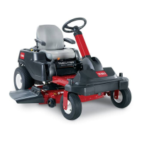
disconnectthechargerleadsfromthebattery
posts(Figure38).
g000538
Figure38
1.Positivebatterypost
3.Red(+)chargerlead
2.Negativebatterypost
4.Black(-)chargerlead
InstallingtheBattery
1.Positionthebatteryinthetray(Figure37).
2.Installthepositive(red)batterycabletothe
positive(+)batteryterminalusingthefasteners
removedpreviously.
3.Installthenegativebatterycabletothenegative
(-)batteryterminalusingthefastenersremoved
previously.
4.Slidetheredterminalbootontothepositive
(red)batterypost.
5.Securethebatterywiththehold-down(Figure
37).
6.Lowertheseat.
ServicingtheFuses
Theelectricalsystemisprotectedbyfuses.Itrequires
nomaintenance;however,ifafuseblows,checkthe
component/circuitforamalfunctionorshort.
Fuse:
•MainF1-30A,blade-type
•ChargeCircuitF2-25A,blade-type
1.Removethescrewssecuringthecontrolpanel
tothemachine.Retainallfasteners
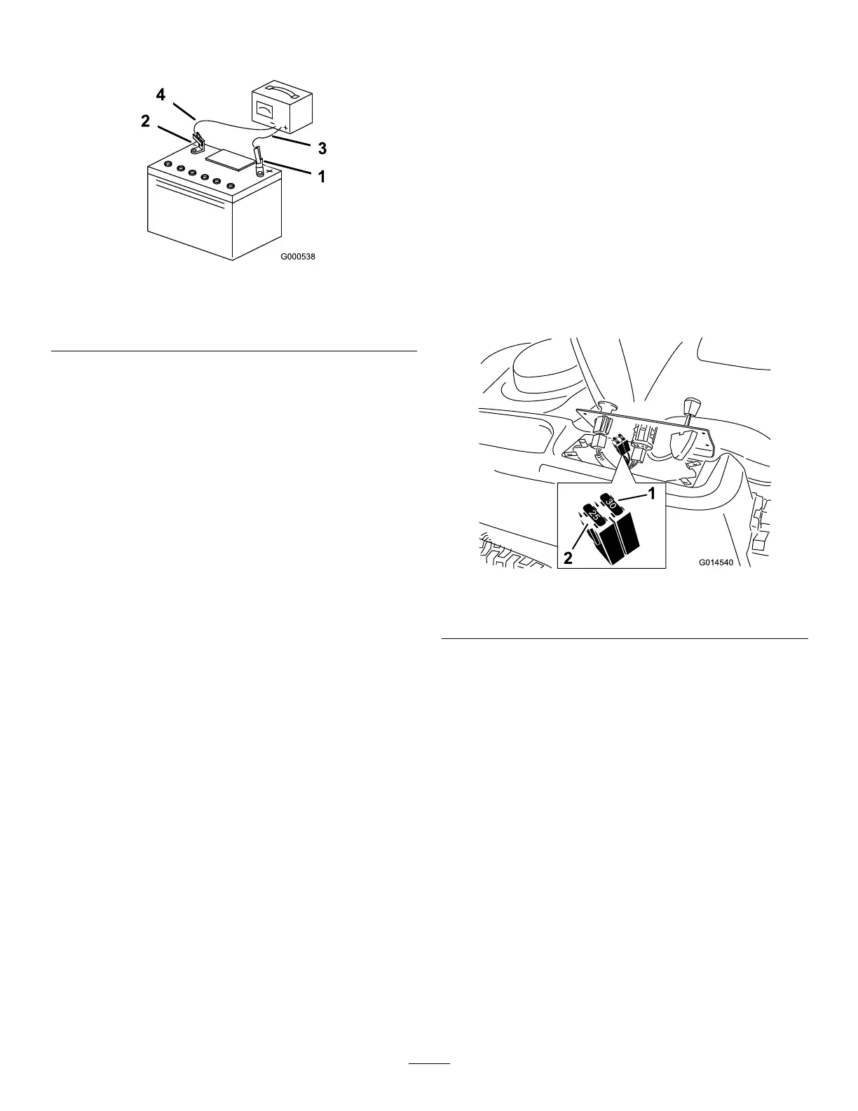
2.Liftthecontrolpaneuptoaccessthemainwire
harnessandfuseblock(Figure39).
3.T oreplaceafuse,pulloutonthefusetoremove
it(Figure39).
g014540
Figure39
1.Main—30A
2.Chargecircuit—25A
4.Returnthecontrolpaneltoitsoriginalposition.
Usethescrewsremovedpreviouslytosecure
thepaneltothemachine.
38
 Loading...