g301336
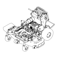
Figure74
1.Hydraulic-tankcap
2.Colduidlevel
5.Removethecapfromthellerneck(Figure74).
Note:Lookinsidetochecktheuidlevelin
thereservoir.
6.Adduidtothereservoiruntilitreachesthe
reachestheminimumcoldlllevel.
7.Installthecaponthellerneck.
ReplacingtheHydraulic
FluidandFilters
ServiceInterval:Aftertherst50hours
Every500hours/Yearly(whichevercomes
rst)—Changethehydraulicltersandhydraulic
uid.
Changethehydraulicuidmorefrequentlyinsevere
conditionsorinahotoperatingclimate.Contact
yourAuthorizedServiceDealerforahydraulickitto
replacethehydrauliclters.
WARNING
Hothydraulicuidcancausesevereburns.
Allowthehydraulicuidtocoolbefore
performinganymaintenanceonthehydraulic
system.
1.Parkthemachineonalevelsurface,disengage
thePTO,andengagetheparkingbrake.
2.Shutofftheengine,removethekey,andwait
forallmovingpartstostopbeforeleavingthe
operatingposition.
3.Removethefueltank;refertoRemovingthe
FuelT ank(page38).
4.Removethehydraulic-reservoircap.
5.Locatethedrainpluginthebottomofeach
transmissionandplaceadrainpanunderthe
plugs(Figure75).
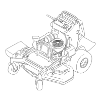
g268090
Figure75
1.Drainplug
2.Hydrauliclter
6.Removethedrainplugs.
7.Allowthehydraulicuidtofullydrainfromthe
machine.
8.Removethehydraulicltercapandlterfrom
eachtransmission.
9.Installnewhydrauliclterswiththespringside
facingoutandinstalltheltercaps.
10.Installthedrainplugsandtorqueto22to27
N∙m(16to20ft-lb).
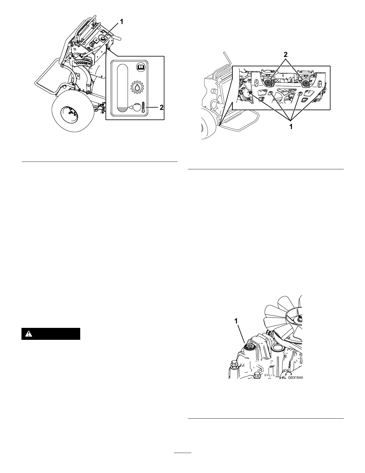
11.Loosentheventplugineachtransmissionso
thatitislooseandwobbles(Figure76).
Note:Thisallowsairtoescapethehydraulic
systemasyouaddhydraulicuid.
g031544
Figure76
Lefttransmissionshown
1.Ventplug
12.Slowlyadduidtothehydraulictankuntilit
startstocomeout1oftheventplugs.
50
 Loading...