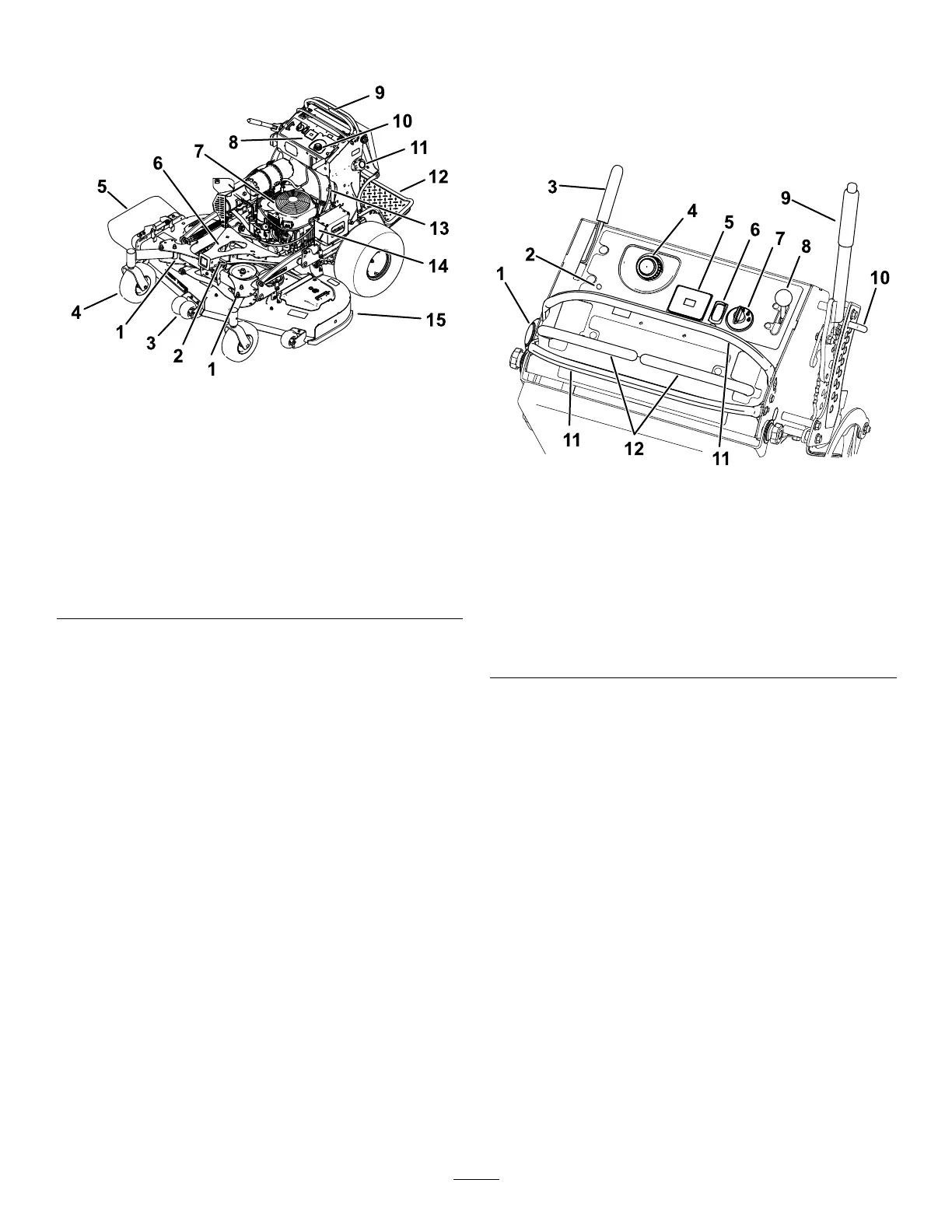
ProductOverview
g306613
Figure3
1.Adjustablecaster9.Motion-controllevers
2.Accessory-framelock
10.Hydraulictank
3.Anti-scalproller(60-inch
decksonly)
11.Fueltank
4.Frontcasterwheel
12.Platform(downposition)
5.Side-dischargechute13.Fuel-shutoffvalve
6.Accessoryframe
14.Battery
7.Engine15.Mowerdeck
8.Controlpanel
Controls
Becomefamiliarwithallthecontrolsbeforeyoustart
theengineandoperatethemachine(Figure4).
ControlPanel
g301785
Figure4
1.Fuelcap7.Keyswitch
2.Malfunction-indicatorlight
(MIL)
8.Throttlecontrol
3.Parking-brakelever
9.Height-of-cutlever
4.Hydraulic-tankcap
10.Height-of-cutpin
5.Hourmeter11.Motion-controllever
6.Power-takeoffswitch
(PTO)
12.Referencebar
Electronic-ControlUnit
Malfunction-IndicatorLight
Theelectronic-controlunit(ECU)continuously
monitorstheoperationoftheEFIsystem.
Ifaproblemorfaultwithinthesystemisdetected,the
malfunction-indicatorlight(MIL)isilluminated(Figure
4).
TheMIListheredlightlocatedintheconsolepanel.
WhentheMILilluminates,makeinitialtroubleshooting
checks;refertoTroubleshooting(page60).
Ifthesechecksdonotcorrecttheproblem,further
diagnosisandservicingbyanAuthorizedService
Dealerisnecessary.
Power-TakeoffSwitch(PTO)
Usethepower-takeoffswitch(PTO)toengageand
disengagemowerbladesorstartandstoppowered
attachments(Figure4);refertoOperatingthe
Power-Takeoff(PTO)Switch(page15).
9
 Loading...