Figure 58
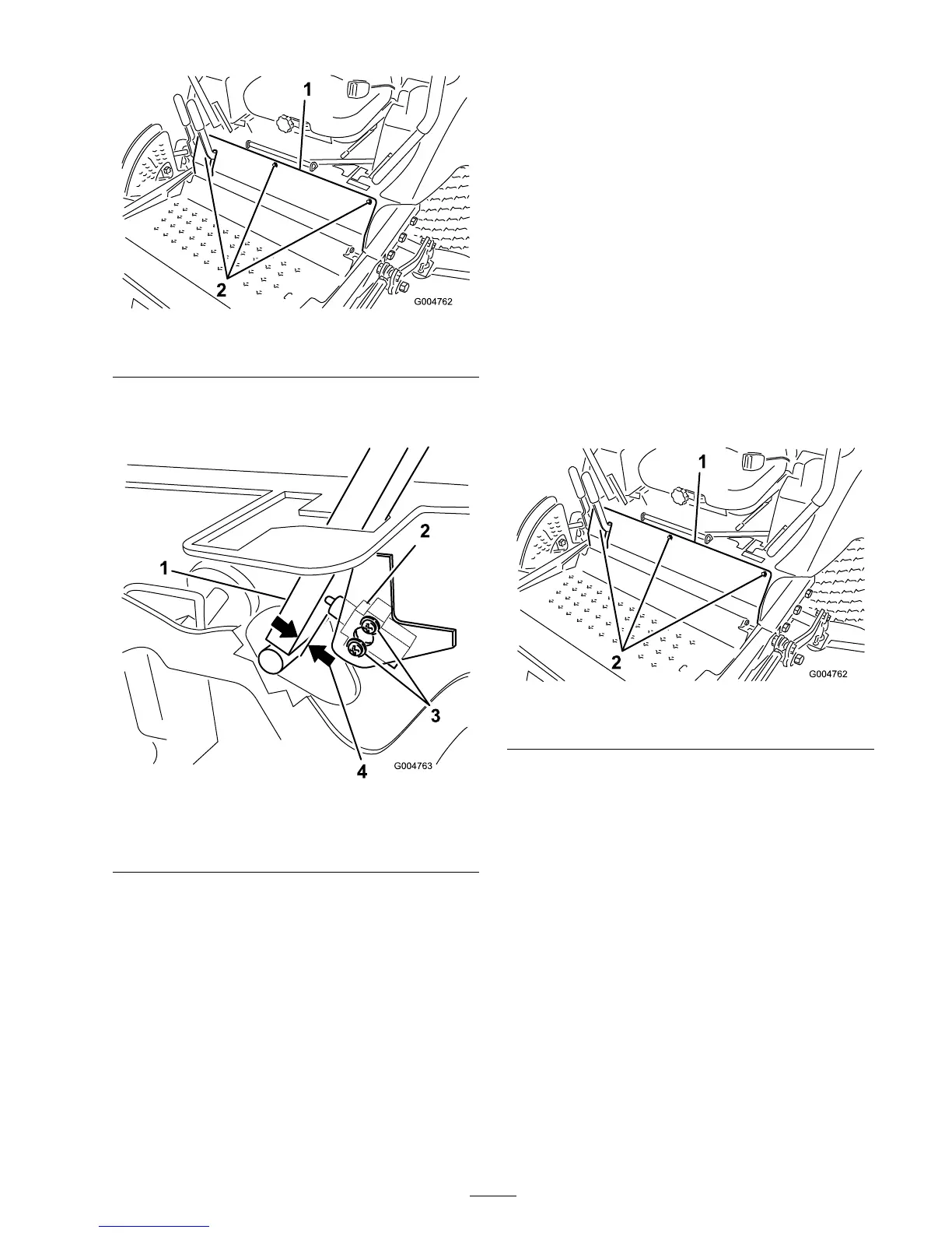
1. Front panel bolts
3. Loosen the 2 screws securing the interloc k
switc h ( Figure 59 ).
Figure 59
1. Control lever
3. Screws
2. Neutral interlock switch
4. 0.015 to 0.045 inch (0.4 to
1 mm)
4. Holding the control lev er ag ainst the frame ,
mo v e the switc h to w ard the lev er until the
distance betw een lev er and switc h body is
0.015 to 0.045 inc h (0.4 to 1 mm) ( Figure 59 ).
5. Secure the switc h.
6. R e peat ste ps 3 to 5 for the other lev er .
7. Install the front panel.
Adjusting the Control Lever
Neutral Return
If the motion control lev ers do not align with the
neutral slots when released from the rev erse dri v e
position, adjustment is required. Adjust eac h lev er ,
spring, and rod se parately .
1. Diseng ag e the PTO , mo v e the motion control
lev ers to the neutral loc k ed position and set
the parking brak e .
2. Mo v e the throttle lev er to the Slo w position,
stop the engine , remo v e the k ey , and w ait for
all mo ving par ts to stop before lea ving the
operating position.
3. R emo v e the bolts securing the front panel and
remo v e the panel ( Figure 60 ).
Figure 60
1. Front panel bolts
4. Mo v e one of the lev ers to the neutral position
but not lock ed ( Figure 62 ).
5. Pull the lev er bac k until the clevis pin (on an
ar m abo v e the pi v ot shaft) contacts the end
of the slot (just beginning to put pressure on
the spring) ( Figure 61 ).
57

 Loading...


