19
INSTALLATION INSTRUCTIONS
RAIN SENSOR PUMP START RELAY CONNECTION
The controller is factory fitted with a link be-
tween terminals R and C. If a Rain Sensor is not
to be used, then leave this link in place.
If a Rain Sensor is to be used, then remove this
link and connect the rain Sensor to terminals
R and C. The Rain Sensor must have normally
closed contacts that open when sucient rain is
sensed.
NOTE
The solenoid valve outputs are 24VAC and
designed to operate a maximum of two
solenoid valves per station. Station current
draw not to exceed 0.5 amps. Maximum
combined current draw including the master
valve/pump start relay and station shall not
exceed 0.8 amps.
Exceeding the maximum current draw may
damage the controller and void the warranty.
CAUTION
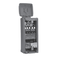
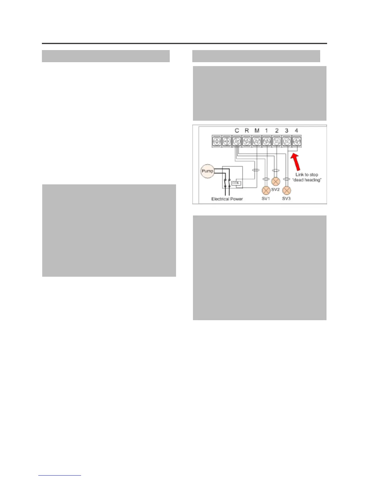
The controller cannot be used to power a
pump motor directly. As shown in the drawing
below, the controller provides 24VAC
(maximum current 0.5A) to switch an auxiliary
relay which switches power to the pump.
CAUTION
To prevent pump damage due to “dead-head-
ing” (the pump is running, a station has inad-
vertently been given a run time but no valve
is connected to the output terminal), connect
a jumper wire from any unused station termi-
nals to a used station terminal, as shown by
the red arrow in the above diagram.
Note: In the instance shown in the diagram
above, station 3 will be activated when the
controller activates station 4
Pump Start Wiring
 Loading...