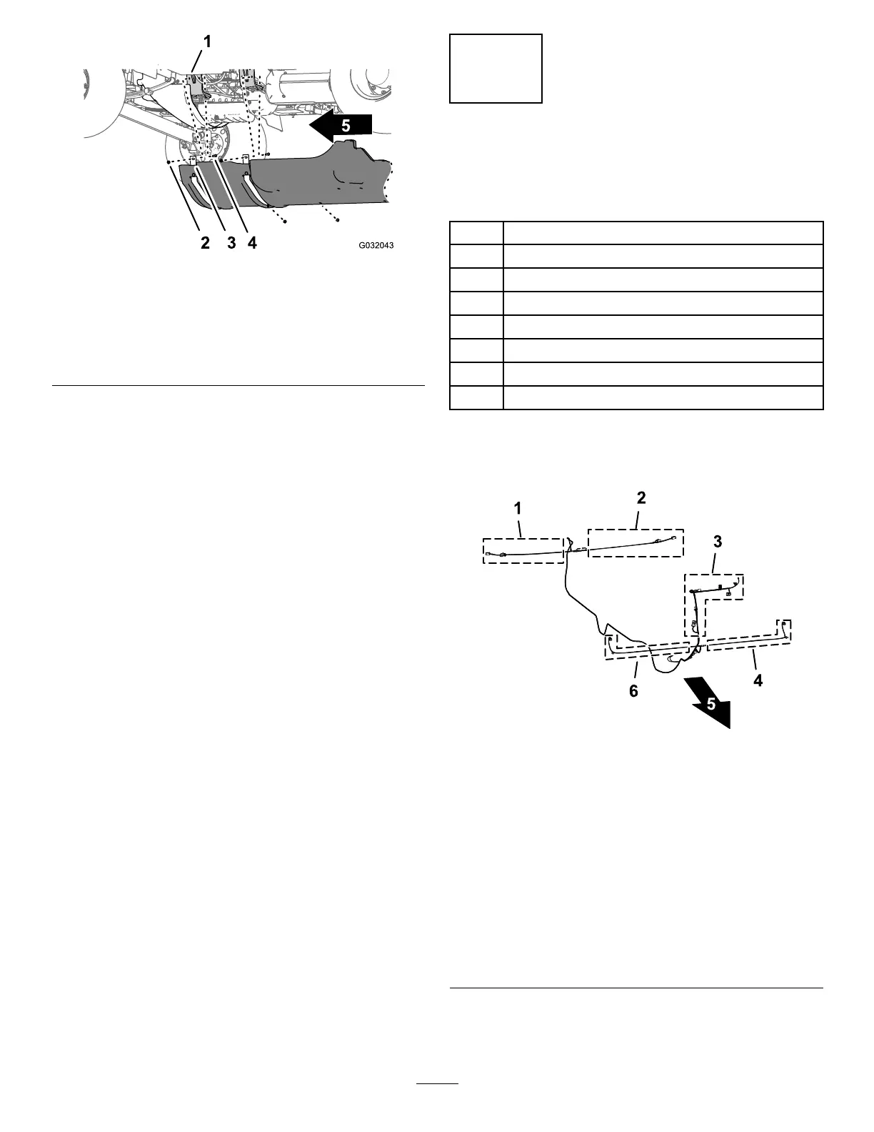
g032043
Figure6
1.Enginemounts
4.Flangelocknuts(5/16
inch)
2.Bolt—shownforclarity;do
notremove
5.Frontofthemachine
3.Undercarriageshroud
3.Liftthesupportstrapsovertheboltsthatsecure
theundercarriageshroudtotheengine-mount
brackets.
4.Removetheundercarriageshroudfromthe
machine(Figure5andFigure6).
3
AssemblingtheWorklight
andWireHarness
Partsneededforthisprocedure:
1WireHarness
1
Grommet
2Worklightmount
1
Supportchannel
4
Flange-headbolt(3/8x2-1/4inches)
4
Spacer
4
Flangelocknut(3/8inch)
2Worklight
AssemblingtheGrommetontothe
WireHarness
g207897
Figure7
1.71cm(28inches)wire
harnessbranch—RIGHT
TURNSIGNAL
4.99cm(39inches)wire
harnessbranch—LEFT
FRONTTURN/RUNNING
LIGHT
2.89cm(35inches)wire
harnessbranch—LEFT
TURNSIGNAL
5.Forward
3.108cm(42-1/2
inches)wireharness
branch—hornswitch,TO
HEADLIGHTSWITCHPIN1,
turnsignal,hazardswitch,
CEashermodule,andTO
MAINHARNESS
6.112cm(44inches)wire
harnessbranch—RIGHT
FRONTTURN/RUNNING
LIGHT
1.Alignthe6-socketconnectorfortheRIGHTFRONT
TURN/RUNNINGLIGHTofthe112cm(44inches)
wireharnessbranchthroughthegrommetand
5

 Loading...