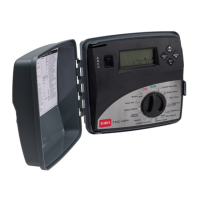
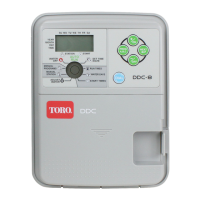
1- Service Reset Button
Facilitates controller CPU initial-
ization (for service only).
2- 9-V battery compartment
3- 9-V battery clip
Battery required for Armchair
Programming. Keep attached to
TM when battery is not used.
4- Program Switch
A four-position slide switch used
to select program A, B, C and D
for set up, review and manual
operations.
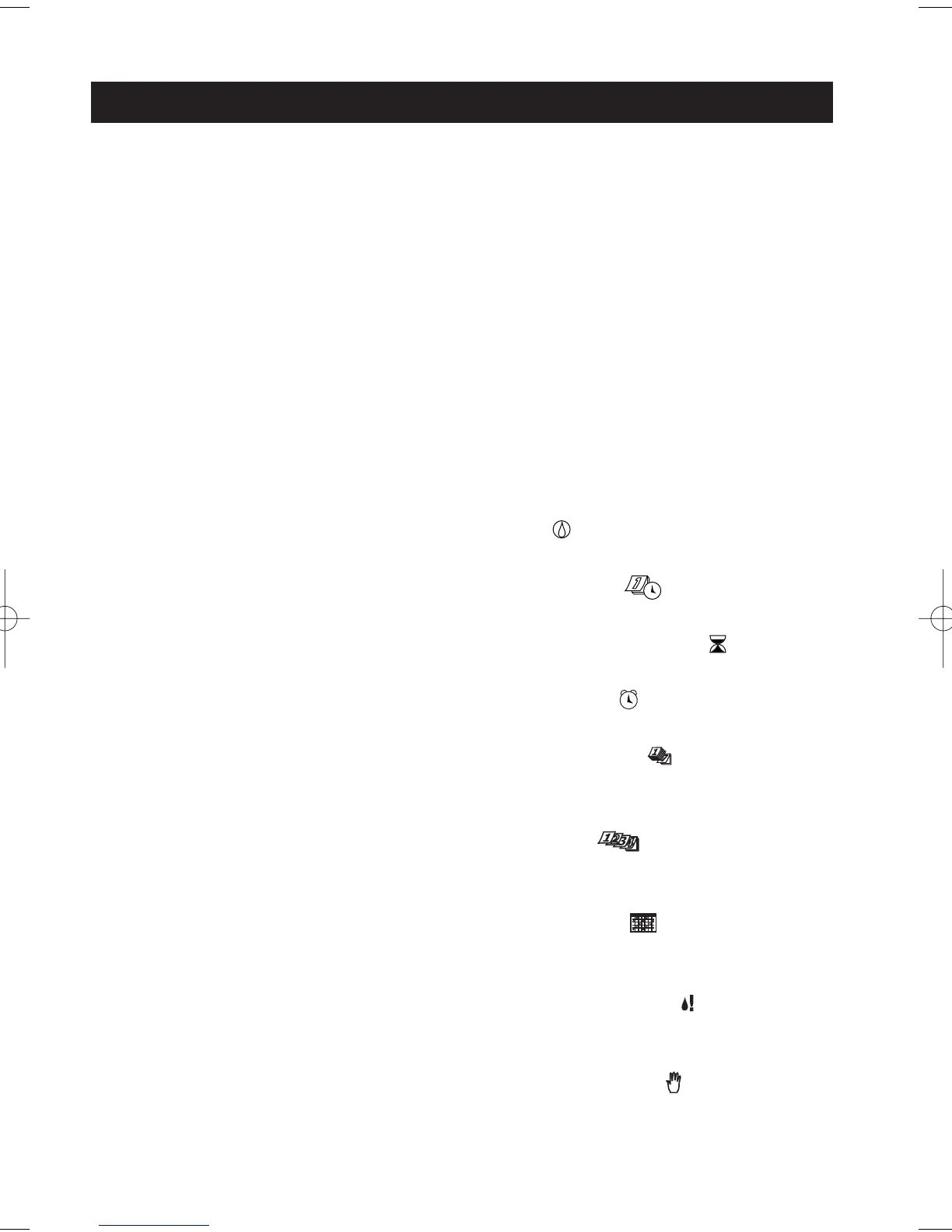
5- Digital Display
a- Station run time icon.
b- Start time icon.
c- Program identifiers.
d- Prompt displayed with Interval
schedule length
e- Flow sensor icon indicates bay
location of flow module.
f- % symbol is displayed when
water budget function is applied.
g- Water drop icon indicates water
On and Off (slash).
h- Prompt displayed to indicate
current position in an Interval
watering day schedule.
i- Expansion module bay identifier
(I, II and III, left to right).
j- Expansion module station
identification numbers.
6- Navigation Buttons
Left and right arrow buttons to
index through display menu items
for each dial setting.
Up and down arrow buttons
change time/percentage values
and select Yes/No options.
7- Function Dial
Turns in either direction to select
the following operating, control
and programming functions:
RUN – Home dial position for
automatic controller operations.
SET TIME/DAY – Set the clock
time, day and date.
SET STATION RUN TIMES – Set the
run time for each station.
START TIMES – Set the program
start times.
CALENDAR DAYS – Set program
watering day schedule by days of
the week.
ODD/EVEN – Set program
watering day schedule by Odd or
Even numbered days.
DAY INTERVAL – Set program
watering day schedule by interval
period from 1 to 31 days.
SPECIAL FUNCTIONS – Provides
menu of options for set up, control
and timing features. (See page 9.)
MANUAL STATIONS – Enables
individual stations to be operated
manually.
2
The following brief descriptions of the controller components and display
elements are provided for general overview. Each of these items will be
explained in further detail in the appropriate section of this guide.
Controller Components

 Loading...