ProductOverview
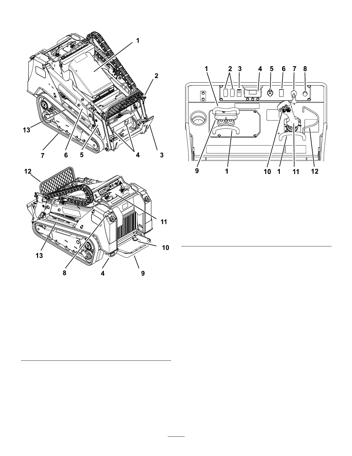
g303491
Figure11
1.Hood8.Fuelgauge
2.Auxiliaryhydraulic
couplers
9.Operatorplatform
3.Mountplate10.Auxiliaryhydraulicslock
switch
4.Tie-downloop
11.Controlpanel
5.Lowerloaderarm12.Debrisshield
6.Upperloaderarm
13.Cylinderlock
7.Track
Controls
ControlPanel
Becomefamiliarwithallthecontrols(Figure12)before
youstarttheengineandoperatethetractionunit.
g300633
Figure12
1.Referencebar
7.Keyswitch
2.Plug8.Horn
3.Parkingbrakeswitch9.Tractioncontrol
4.InfoCenter
10.Joystickcontrols
5.Powersocket
11.Loaderarm/attachment-tilt
lever
6.Throttleswitch12.Loader-valvelock
KeySwitch
Thekeyswitch,usedtostartandshutofftheengine,
has3positions:OFF,RUN,andSTART.Referto
StartingtheEngine(page22).
Parking-BrakeSwitch
Presstheparking-brakeswitchtoengageand
disengagetheparkingbrake(Figure12).Theparking
brakealsoengagesautomaticallywhenyoushutoff
themachine.
ThrottleSwitch
Presstheswitchforwardfor2ormoresecondstoset
thethrottleatHIGHIDLE;presstheswitchrearward
for2ormoresecondstosetthethrottleatLOWIDLE;
ormomentarilypresstheswitchineitherdirectionto
increaseordecreasetheenginespeedin100-rpm
increments.
11

 Loading...


