40-EN39-EN
– 0 2 –
*10: Extension up till 90 m is possible with conditions below
- Outdoor Temperature Cooling : 10°C to 46°C (Dry-bulb temp.)
Heating : -5°C to 15°C (Wet-bulb temp.)
Simultaneous operating : 7°C to 25°C (Dry-bulb temp.)
- Equivalent length of farthest piping from first branching Li < 50 m
- Actual length of main piping L1 < 100 m
- Height difference between indoor units H2 < 3 m
- Single CDU, and up to 18 HP
- Minimum capacity of connectable indoor : unit 036 type or Larger
- Height difference between FS units < 0.5 m
- The total value of capacity codes of the connectable indoor units to the capacity code of the outdoor unit : 90% to 100%
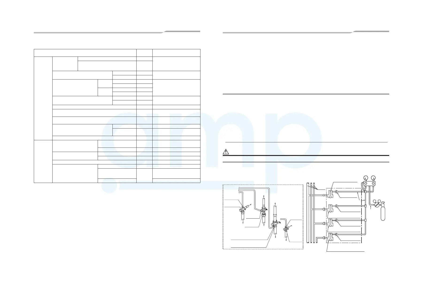
Airtightness test
After the refrigerant piping has been finished, execute an airtight test.
For an airtight test, connect a nitrogen gas canister as shown in the figure on this page and apply pressure.
• Be sure to apply pressure from the service ports of the packed valves (or ball valves) at the suction gas side,
discharge gas side, liquid side and balance pipe side.
• An airtight test can only be performed at the service ports at the suction gas side, discharge gas side, liquid side
and balance pipe side.
• Close the valves fully at the suction gas side, discharge gas side, liquid side and balance pipe side. As there is
a possibility that the nitrogen gas will enter into the cycle of outdoor units, re-tighten the valve rods at the liquid
side and balance pipe side before applying pressure.
• For each refrigerant line, apply pressure gradually in steps at the suction gas side, discharge gas side, liquid
side and balance pipe side.
Be sure to apply pressure at the suction gas side, discharge gas side, liquid side and balance pipe side.
WARNING
Never use oxygen, flammable gases, or noxious gases in an airtight test.
VL
V
H
Packed valve details
To gauge
manifold
Liquid-side
service port
Liquid-side
valve
Piping at site
To
outdoor
unit
Piping
at site
To outdoor unit
Piping
at site
Connected to
other follower units
Main
piping
Connected to
indoor unit
Low pressure
gauge
High pressure
gauge
Gauge
manifold
Reducing
valve
Ø6.4
copper
pipe
Nitrogen
gas
Balanced pipe side valve
fully closed
Liquid side valve fully closed
Discharge gas side valve
fully closed
Fully
closed
Fully
closed
Fully
closed
Brazed
Suction gas side valve
fully closed
Header outdoor unit
Ø6.4 copper pipe
Service port
Service port
Service port
Service port
Piping
at site
Ball valve of suction gas side
Service port of suction gas side
Service port
of discharge
gas side
Ball valve of
discharge
gas side
To outdoor
unit
To
gauge
manifold
Service
port
of balance
pipe side
Packed
valve
of balance
pipe side
To
outdoor
unit
¿ Allowable length and allowable height difference of refrigerant piping
Item
Allowable
value
Pipes
Pipe length
Total extension of
pipe (liquid pipe,
real length)
Less than 34 HP or less 300 m
LA + La + Lb + Lc + L1 + L2 + L3 +
a + b + c + d + e + f + g + h + i + j + k
+ l + m + n + o+ p + q + r + s + t + u + v
34 HP or more
1000 m
(*7)
Farthest piping length L (*1) (*2)
Equivalent length 200 m
LA+Lc+L1+L3+L4+L5+L6+L7+L8+o
Real length 180 m
Max. equivalent length of Main
piping
H2 > 3 m
Equivalent length 100 m
L1
Real length 85 m
H2 ≤ 3 m
Equivalent length 120 m
Real length 100 m
Farthest equivalent piping length from the first
branch Li (*1)
H1 > 3 m 50 m
H1 [ 3 m
65 m
Farthest equivalent piping length between outdoor units LO (*1) 15 m LA+Lc (LA+Lb)
maximum equivalent piping length of pipes connected to outdoor
units
10 m Lc (La, Lb)
Maximum real length of terminal branching section to indoor
units
a+f, b+g, c+h, d+i, e+j, k, l,L6+L7+L8+o(Ln)
Maximum real length of between Flow Selec-
tor unit and indoor unit
Single port type 15 m f, g, h, i, j,L7+m,L7+L8+o
Multi port type
50 m
(*8) (*9)
p, q, r,L11+s,L11+t,L13+u,L13+v
Maximum equivalent length between branching section 50 m L2, L3, L4, L5, L9, L10, L12
Height
difference
Height between outdoor and
indoor units H1
Upper outdoor units
70 m
(*6)(*10)
‒
Lower outdoor units 30 m (*5) ‒
Height between indoor units
H2
Upper outdoor units 40 m ‒
Lower outdoor units (*3) 15 m ‒
Height between outdoor units H3 (*4) 5 m ‒
Single port type
*1: Farthest outdoor unit from the first branch: (C), farthest indoor unit: (o)
*2: Allowable values for length equivalent to furthest pipe are shown below and they vary according to performance rank of outdoor
unit.
22.4 to 56.0: 185m, 61.5 to 112.0: 195m, 120.0: 200m
*3: When system capacity is greater than 28 HP, height difference between indoor units is limited to 3 m. If the piping exceeds 3 m
with a capacity greater than 28 HP there may be a case of capacity shortage in cooling.
*4: Ensure that the header unit is installed below all connected follower outdoor unit(s).
Possible product failure may occur if header unit is installed above any follower unit(s).
*5: 40m is possible for a system that uses only the flow selector unit (multi port type), whose all the indoor units are 3HP or higher,
and working ambient temperature is 0ºC or higher.
*6: If the height difference (H2) between indoor units exceed 3 m, set 50 m or less.
*7: Total charging refrigerant is 140 kg or less.
*8: The total piping length in one Multi port type FS unit in case of branching to 4 : 120m (p + q + r + L11 + s + t), In case of branching
(LA+Lc+L1+L3+L9+L10+L11+t)
(LA+Lc+L1+L3+L9+L12+L13+v)
(L3+L9+L10+L11+t) (L3+L9+L12+L13+v)
30 m
Single port type
(Long piping model)
Height difference between indoor
0.5 m
3 m
Single port type
H4
(Long piping model) H6
Multi port type H5
*9: Length of whole pipe should be shorter than 50 m (L11+s+t, L13+u+v) in one branch.
to 6 : 180m.
L3+L4+L5+L6+L7+L8+o
units in one Flow Selector unit
‒
‒
‒
L4 + L5 + L6 +L7 + L8 + L9 + L10 +
L11 + L12 + L13 + L14 +
www.ampair.co.uk | sales@ampair.co.uk
 Loading...