–4–
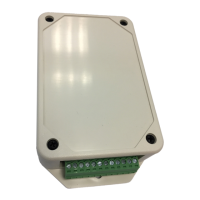
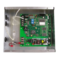
Modbus Interface
Installation Manual
EN
3 Before installation
Check the following package contents.
Use the following wiring materials to connect the communication cables and power cables. (locally procured)
4 Installation
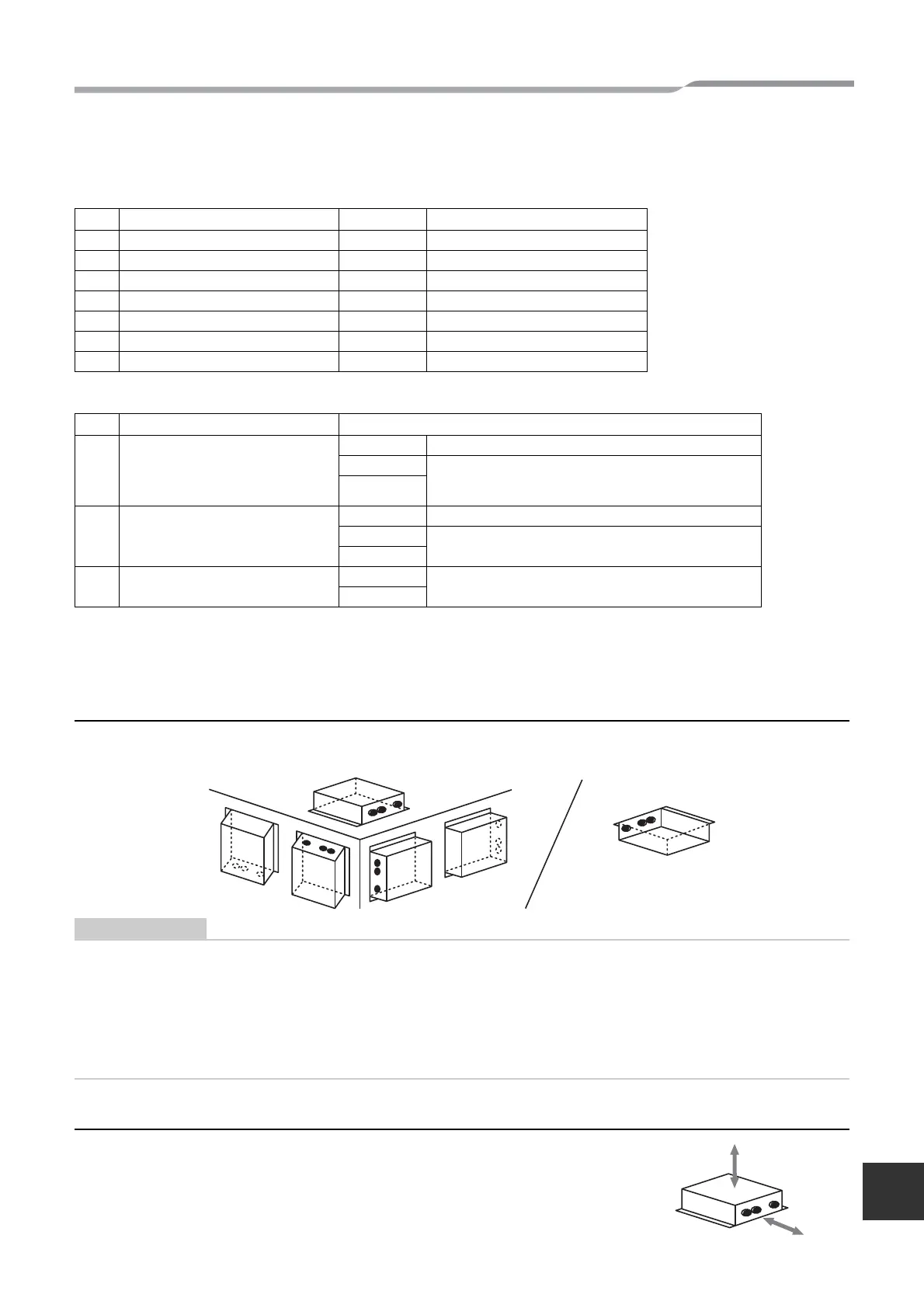
Modbus Interface installation method and orientation
There are five installation methods for this Modbus Interface as shown below: surface mount and wall mounts. Use
the attached screws.
Do not install the unit in any of the following places.
• Humid or wet place
• Dusty place
• Place exposed to direct sunlight
• Place where there is a TV set or radio within one meter
• Place exposed to rain (outdoors, under eaves, etc.)
Installation space and maintenance space
A side space for connecting through cable inlets and an upper space for maintenance
must be reserved before installation.
The other sides can be adjacent to surrounding objects.
No. Item Quantity Remarks
1 Modbus Interface 1
2 Installation Manual 1
3 Screw 4 M4 x 12 mm tapping screws
4 Cable clamp 1
5 Clamp filter 1
6 Tie-wrap 1 For fixing the clamp filter
7CD-R 1
No. Line Description
1 For TCC-LINK
Type 2-core shielded wires
Wire size
1.25 mm
2
, 1000 m max.
2.00 mm
2
, 2000 m max.
(total length including air conditioner area)
Length
2 For RS-485
Type 2-core shielded wires
Wire size
1.25 mm
2
, 500 m max.
(total length)
Length
3 For power
Type
H07 RN-F or 245IEC66
0.75 mm
2
, 50 m max.
Wire size
4-EN
 Loading...