–5–
Modbus Interface
Installation Manual
5 Connection of power cables / earth wires /
communication cables
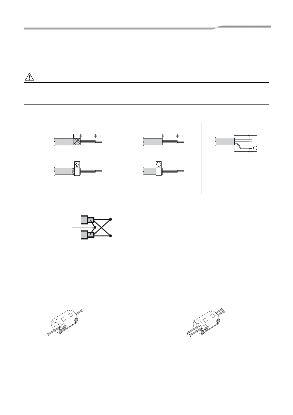
• The RS-485 communication cables have polarity. Connect A(+) to A(+), and B(-) to B(-). If connected with incorrect
polarity, the unit will not work.
• The TCC-LINK communication cable have no polarity.
Connect power cables, earth wires, and communications cables to the specified terminals on the terminal block.
Attach the provided Clamp filter to the communication cable.
• Attach the Clamp filters to the RS-485 communication cable as shown below. Fix them to the communication
cables with cable ties.
• Attach the Clamp filters as close as possible to the Modbus Interface unit.
Length of stripped RS-485
(Shielded wire ends) and TCC-
LINK communication cable
Length of stripped RS-485 communication
cable (not shielded wire ends)
Length of stripped power cable
Do not connect the shield wire
to the earth. It should be open
and insulated.
Clamping communication cableClamping RS-485 communication cable
(address 1)
The RS-485 communication cable must be earthed
on address 1 (Modbus Interface address SW=1)
Modbus Interface. Fix the shielded wire of RS-485
communication cable with metal cable clamp and
screw it to the chassis to earth it.
A(+)
B(-)
The shielded wires must be crimped with closed
end connectors on interfaces with address of other
than 1 and not shielded wire ends.
Shielded wires
To connect 1 cable To connect 2 cables
5-EN
 Loading...