–8–
Modbus Interface
Installation Manual
EN
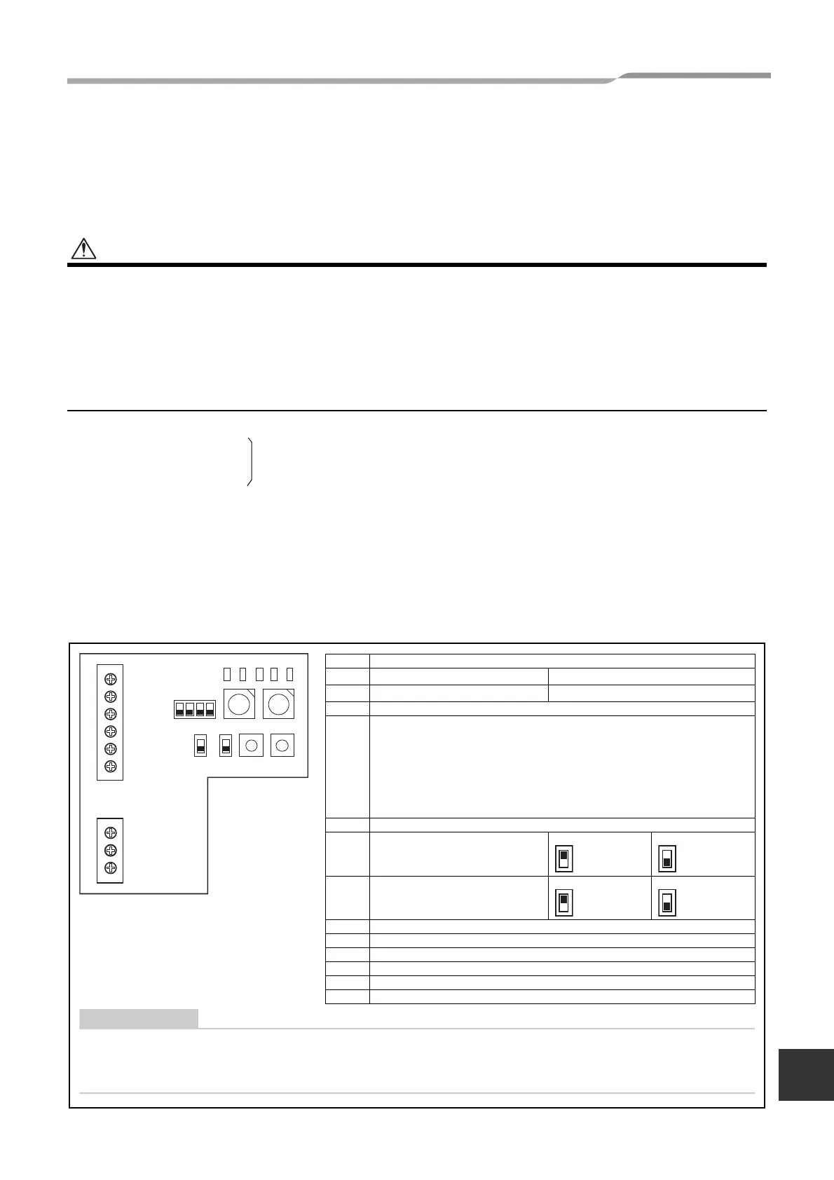
6 Setting
The following settings are necessary to use Modbus Interface.
• SW1 Modbus Interface address set switch
When two or more Modbus Interface are used, set a different address for SW1 to avoid address
duplication. Assign addresses in an ascending order.
•
For the Modbus Interface whose address SW1=1, perform terminator resistor setting.
•
When the SW1 setting has been changed, press the reset switch SW7. The new address setting is read.
•
To clear all accumulated operating values to 0, set SW2 to 3 and press the reset switch SW7, and then set SW2
to 0 and press the reset switch SW7 again.
•
To set the delayed response mode, set SW2 to 4 and press the reset switch SW7. With this mode, a slave delays
responding to the requests from the master for 250ms.
Leave SW2 set to 4 to keep the response mode set as delayed response mode.
•
When the setting of bit3 and bit4 of SW3 has been changed, press the reset switch SW7. The new set value is read.
• SW2 Test switch Not used during operation. Set these switches to zero (0) or “all OFF”.
• SW3 Test switch Bit1: Switches the Modbus Interface software.
Bit2: Switches the LED5 display for test runs.
Bit3, 4: RS-485 baud rate setting (9600/19200/38400) bps.
• SW4 Test switch Not used during operation.
• SW5 RS-485 terminator resistor select switch
Set “120 ohm” only when the Modbus interface address SW=1, and set “open” for other Modbus
interfaces.
• SW6 TCC-LINK terminator resistor select switch
The TCC-LINK terminator resistor is set on the air conditioner side. Set SW6 to “open”.
• SW7 Reset switch
When performing an address setting with SW1, push this reset switch after the address setting to read
the set value.
U1 U2 FG
A
BSG L N
TCC-LINK RS-485
SW1
SW4
LED1
LED2
LED3
LED4
LED5
SW2
SW7SW6SW5
SW3
1234
• RS-485 terminator resistor select switch SW5.
Set “120 ohm” only when the Modbus Interface address SW=1, and set “open” for other Modbus interfaces.
• The TCC-LINK terminator resistor is set on the air conditioner side. Set SW6 to “open”.
SW1 Modbus Interface address set switch
1-F Modbus Interface address
0 Not used
SW2 Test switch (0 usually)
SW3
Bit1: Switches variable specification.
OFF TCB-IFMB641TLE mode, ON TCB-IFMB640TLE mode.
Bit2: Switches the LED5 display for test runs.
OFF RS-485 communication status indicator.
ON TCC-LINK communication status indicator.
Bit3, 4: RS-485 baud rate setting (9600/19200/38400) bps.
3 OFF, 4 OFF 9600 bps, 3 ON, 4 OFF 19200 bps,
3 OFF, 4 ON 38400 bps, 3 ON, 4 ON 19200 bps.
SW4 Test switch
SW5
RS-485 terminator resistor select
switch
120 ohm Open
SW6
TCC-LINK terminator resistor select
switch
100 ohm Open
SW7 Reset switch
LED1 Power indicator
LED2 RS-485 communication status indicator
LED3 TCC-LINK Communication status indicator
LED4 TCC-LINK Communication error indicator
LED5 Test indicator
ON
ON
8-EN
 Loading...