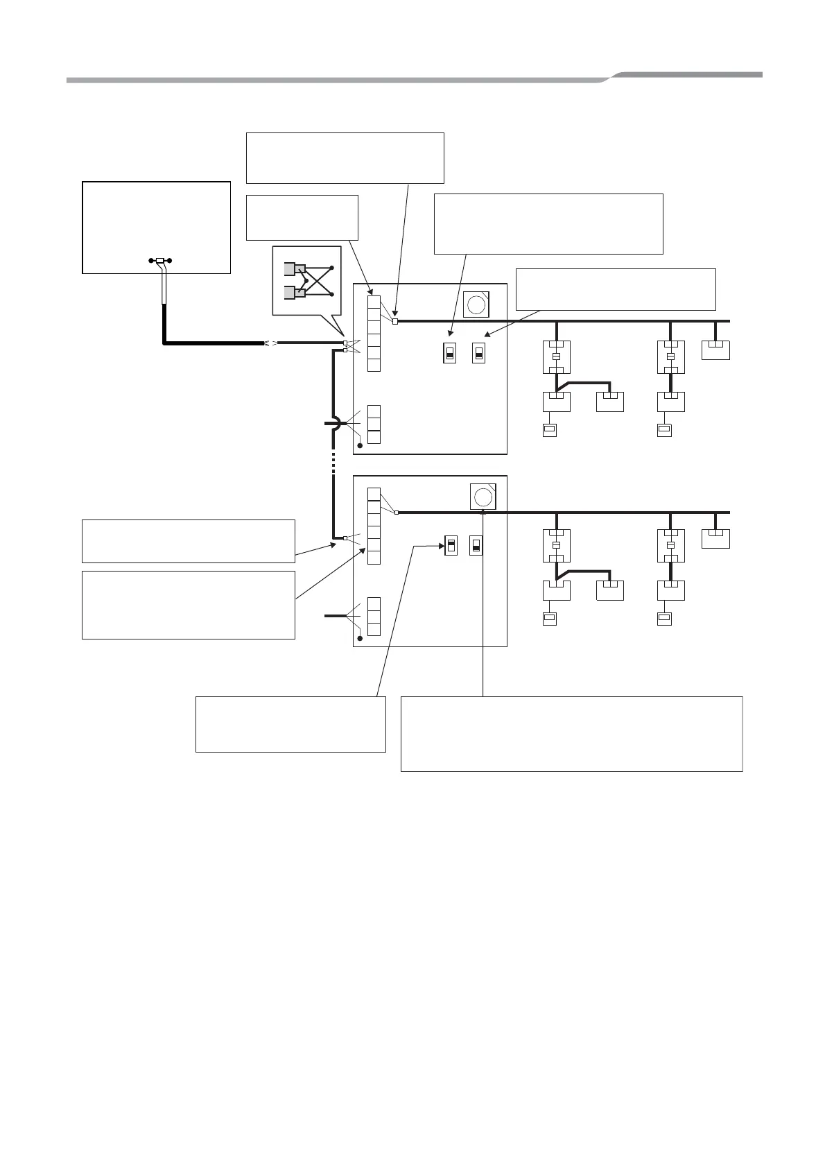
Indoor unit
Do not connect the shielded wire of
TCC-LINK communication cable to
the earth.
Power supply
Indoor unit
Indoor unit
Indoor unit
Indoor unit
Indoor unit
Outdoor
unit
Outdoor
unit
Outdoor
unit
Outdoor
unit
Remote
controller
Remote
controller
Remote
controller
Remote
controller
Power
supply
Central remote
controller
Central remote
controller
TCC-LINK U1 and
U2 have no polarity.
Set the RS-485 terminator resistor on the
address1 unit (Modbus Interface address
SW1=1) and host system. Do not set it here.
TCC-LINK terminator resistor is set on
the air conditioner side. SW6 should
be OFF.
The shielded wire of the RS-485
communication cable must be earthed
on address 1
CAUTION: RS-485 communication
cables A(+) and B(-) have polarity.
Be careful when connecting the RS-
485 wires.
RS-485 terminator resistor is set by
Modbus interface of address setting
switch SW1=1 only.
Set the Modbus Interface address with SW1. Assign 1 to
F(15) to each address to avoid duplication.
CAUTION: The SW1 setting is read when the power is
turned on. Push the reset switch SW7 after changing the
address.
Modbus-Master
(Locally procured)
 Loading...