EasyManuals Logo

Toyota 4RUNNER 2007 User Manual

Toyota 4RUNNER 2007
500 pages
To Next Page IconTo Next Page
To Previous Page IconTo Previous Page
Page #135 background imageLoading...
Page #135 background image
134
4RUNNER (EM03M0U)
Headlight
(w/ daytime running light)
This system is designed to automatically activate the turn signal lights during the daytime to keep the car highly visible to
other vehicles. This system is controlled by the body ECU.
This system makes use of the turn signal lights as daytime running lights.
For this reason, when the turn signal lights are operated, the daytime running lights function is interrupted momentarily,
which, however, will be brought back into operation as soon as the interposed operation is over.
This system is enabled when the conditions given below are met.
A) Ignition switch ON condition
B) Turn signal light switch OFF condition
C) Hazard light switch OFF condition
D) Light control switch OFF condition
E) Parking brake switch OFF condition (Parking brake out of operating condition)**
**: This system does not become active when the parking brake switch is ON. However, once the OFF signal of the
parking brake switch is input into the body ECU, this system will become active thereafter, regardless of whether the
parking brake switch is ON or OFF.
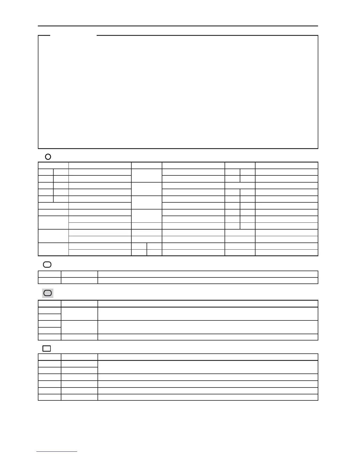
: Parts Location
Code See Page Code See Page Code See Page
B4 A 36
H1
32 (2UZ–FE) J12 A 38
B5 B 36
H1
34 (1GR–FE) J13 B 38
B6 C 36
H2
32 (2UZ–FE) J15 38
C10 C 37
H2
34 (1GR–FE) J18 A 38
C11 D 37
H3
32 (2UZ–FE) J19 B 38
C12 37
H3
34 (1GR–FE) J20 A 38
D2 37
H4
32 (2UZ–FE) J21 B 38
F5
32 (2UZ–FE)
H4
34 (1GR–FE) J22 A 38
F5
34 (1GR–FE) H11 37 J23 B 38
F6
32 (2UZ–FE) J5 38 J24 38
F6
34 (1GR–FE) J7 38 J37 38
G2
32 (2UZ–FE) J10 A 38 P4 39
G2
34 (1GR–FE) J11 B 38
:
Relay Blocks
Code See Page Relay Blocks (Relay Block Location)
2 22 Engine Room R/B (Engine Compartment Left)
:
Junction Block and Wire Harness Connector
Code See Page Junction Block and Wire Harness (Connector Location)
1B
24
Engine Room Main Wire and Driver Side J/B (Lower Finish Panel)
1E
24
Engine Room Main Wire and Driver Side J/B (Lower Finish Panel)
1H
25
Instrument Panel Wire and Driver Side J/B (Lower Finish Panel)
1J
25
Instrument Panel Wire and Driver Side J/B (Lower Finish Panel)
3F 28 Instrument Panel Wire and Center J/B (Instrument Panel Brace RH)
:
Connector Joining Wire Harness and Wire Harness
Code See Page Joining Wire Harness and Wire Harness (Connector Location)
EA1 44 (2UZ–FE)
Engine No.2 Wire and Engine Room Main Wire (Under the Engine Room R/B)
EA2 45 (1GR–FE)
Engine No.2 Wire and Engine Room Main Wire (Under the Engine Room R/B)
IC4 46 Instrument Panel Wire and Engine Room Main Wire (Left Kick Panel)
IH1 46 Instrument Panel Wire and Instrument Panel Wire (Behind the Combination Meter)
IM1 47 Engine Wire and Instrument Panel Wire (Right Side of Blower Unit)
IN1 47 Instrument Panel Wire and Engine Room Main Wire (Right Kick Panel)
System Outline

Table of Contents

Questions and Answers:

Question and Answer IconNeed help?

Do you have a question about the Toyota 4RUNNER 2007 and is the answer not in the manual?

Toyota 4RUNNER 2007 Specifications

General IconGeneral
BrandToyota
Model4RUNNER 2007
CategoryAutomobile
LanguageEnglish

Related product manuals