10 18-AC104D1-1G-EN
Section 12. Electrical - High Voltage
12.1 High Voltage Power Supply
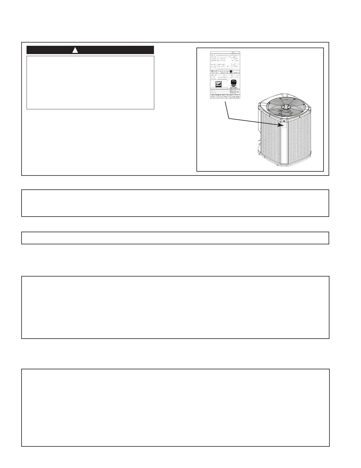
The high voltage power supply must agree with
the equipment nameplate.
Power wiring must comply with national, state,
and local codes.
Follow instructions on unit wiring diagram located
on the inside of the control box cover and in this
document included with the unit.
LIVE ELECTRICAL COMPONENTS!
During installation, testing, servicing, and
troubleshooting of this product, it may be nec-
essary to work with live electrical components.
Failure to follow all electrical safety precau-
tions when exposed to live electrical compo-
nents could result in death or serious injury.
12.2 High Voltage Disconnect Switch
12.3 High Voltage Ground
Ground the outdoor unit per national, state, and local code requirements.
Install a separate disconnect switch at the outdoor unit.
For high voltage connections, flexible electrical conduit is recommended whenever vibration transmission may
create a noise problem within the structure.
Section 13. Start Up
13.1 System Start Up
STEP 1 - Ensure Sections 7 through 12 have been completed.
STEP 2 - Set System Thermostat to OFF.
STEP 3 - Turn on disconnect(s) to apply power to the indoor and outdoor units.
STEP 4 - Wait one (1) hour before starting the unit if compressor crankcase heater accessory is used and the
Outdoor Ambient is below 70ºF.
STEP 5 - Set system thermostat to ON.
STEP 1 - Check the outdoor temperatures.
Subcooling (in cooling mode) is the only recommended method of charging above 55º F ambient outdoor tem-
perature. See Section 14.2.
For outdoor temperatures below 55º F, see Section 14.3.
Note: It is important to return in the spring or summer to accurately charge the system in the cooling mode when
outdoor ambient temperature is above 55º F.
For best results the indoor temperature should be kept between 70º F to 80º F.
Section 14. System Charge Adjustment
14.1 Temperature Measurements
 Loading...