18-AC104D1-1G-EN 9
11.2 Low Voltage Hook-up Diagrams
Section 11. Electrical - Low Voltage
11.1 Low Voltage Maximum Wire Length
Table 11.1 defines the maximum total length of
low voltage wiring from the outdoor unit, to the
indoor unit, and to the thermostat.
Table 11.1
24 VOLTS
WIRE SIZE MAX. WIRE LENGTH
18 AWG 150 Ft.
16 AWG 225 Ft.
14 AWG 300 Ft.
Thermostat Air Handler
Outdoor
Unit
R
G
B
W1
W2
R
B
O
X2
R
G
B/C
B/C
O
Y1
W
Blue
24 VAC HOT
FAN
24 VAC
Common
SOV
COOL/HEAT
1st STAGE
HEATING
2nd STAGE
EMERGENCY
HEAT
Pink Black
White
X2
O
Y1
Y2
Y1
Y2
COOL/HEAT
2nd STAGE
Y2
Thermostat Air Handler
Outdoor
Unit
R
G
B
W1
W2
R
B
O
Y
O
Y
O
X2
R
G
O
Y
l
W
Blue
O
Y2
Y
l
24 VAC HOT
FAN
24 VAC
Common
SOV
COOL/HEAT
1st STAGE
Y2
Y2
COOL/HEAT
2nd STAGE
HEATING
2nd STAGE
EMERGENCY
HEAT
Pink Black
White
X2
Units with pigtails require wirenuts for connections.
In systems with multiple stages of electric heat, jumper W1 and W2 together if comfort control has only one stage of heat.
** TEM6 only - When using a BK enabled comfort control, cut BK jumper and bypass Y1 and Y2 at the air handle
r. Connect BK from
comfort control to BK of the air handle
r
TAM7 only - When using a BK enabled comfort control, cut BK jumper on the AFC and connect BK from comfort control to BK of
.
T
AM7 DIP switches must be configured for “HP: 2-Stage/1 Compressor”.
Note: Refer to Indoor Unit Literature for proper configuration.
BK
WH/BLK
BK
WH/BLK
BK
WH/BLK
BK
WH/BLK
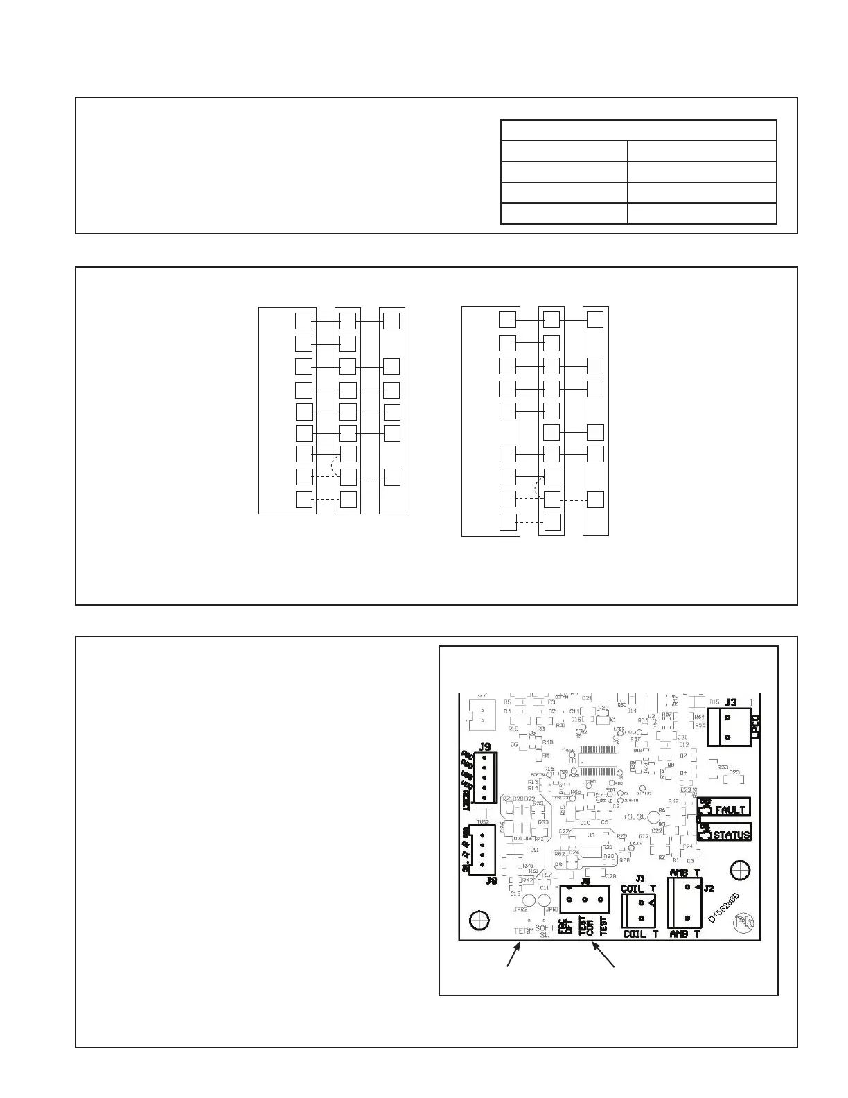
11.3 Defrost Control
Defrost controls have a selectable termination tem-
perature. As shipped, defrost will terminate at 47°F.
For a higher termination temperature, cut Jumper
J2 to achieve 70°F. Refer to the Defrost Control
section in this document for more information.
Pin Identification on J5 (See Illustration)
1. TEST_COMMON (Shorting to FRC_DFT
causes the control to initiate Forced Defrost.
Leaving this pin open results in the normal
mode of operation.)
2. FRC_DFT = Forced Defrost (Short TEST_
COMMON to this pin for two (2) seconds to
initiate a forced defrost. Remove the short
after defrost initiates.)
Defrost Control Checkout
Normal operation requires:
• Status LED on board flashing 1 time/second
in standby or 2 times/second with a call for
heating or cooling.
• 24V AC between R & B
• 24V AC between Y, Y0 & B with unit operating
• Defrost initiation when FRC_DFT pin is shorted to TEST_COMMON pin.
If a defrost control problem is suspected, refer to the service information in control box.
Defrost Board Detail
Jumper J2 J5 Test Pins
 Loading...