34
CAUJ-SVX01E-EN
Table 11. Expansion valve selection, 80 to 120 ton MCHE (15% bleed) (continued)
Min Tonnage Max Tonnage
Manufacturer
Selection
(a)
Trane Part
7 12
Sporlan ERZE-8-ZGA (BP/15)
VAL10581
9.5 15.5
Sporlan ERZE-12-1/2-ZGA (BP/15)
VAL10582
12.5 19
Sporlan ERZE-15-ZGA (BP/15)
VAL10583
15 25
Sporlan OZE-20-ZGA (BP/15)
VAL10584
19.5 30
Sporlan OZE-25-ZGA (BP/15)
VAL10585
23.5 45
Sporlan OZE-35-ZGA (BP/15)
VAL10586
35 68
Sporlan OZE-50-ZGA (BP/15)
VAL10587
52.5 70
Sporlan OZE-60-ZGA (BP/15)
VAL10588
(a)
Valve part numbers with “-ZGA” in place of “-GA”, may be used interchangeably.
Ball Shutoff Valves
The ball shutoff valve allows for isolation of the filter/
filter drier for easier core replacement.
Two ball shutoff valves equal to the OD tubing size for
liquid line are required.
Discharge Line Components
Field supplied hot gas mufflers, pipe anchors, single or
double risers, oil traps, etc. as applicable, should be
provide to prevent excessive line vibration and assure
proper oil return to the compressor for proper system
operation.
A field supplied discharge “shutoff” valve in each hot
gas line near the condenser is recommended to
facilitate refrigerant storage in the condenser during
service procedures.
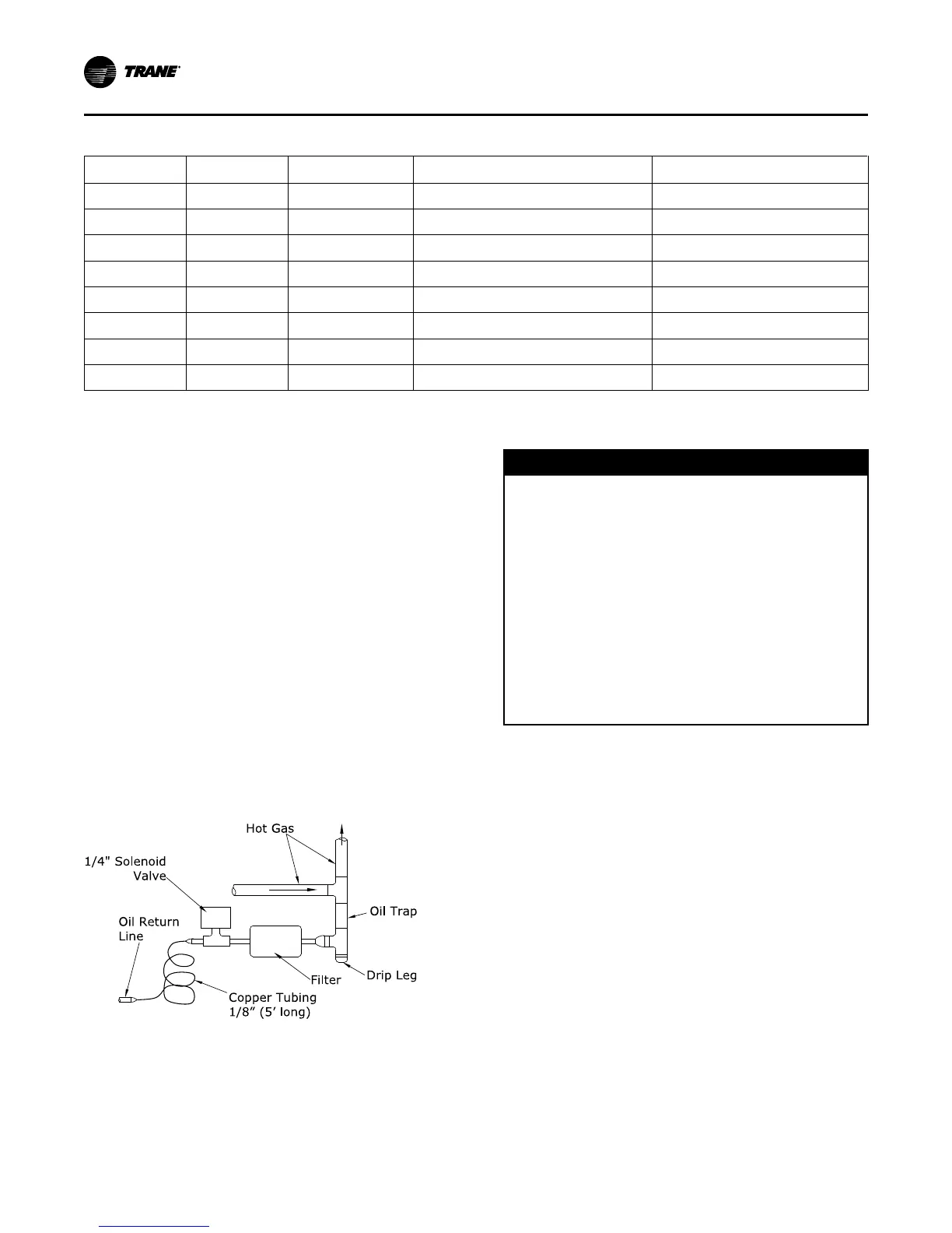
A“constant drain” oil trap is illustrated below and can
be used as an alternative to a double riser application.
The constant drain oil trap assures adequate oil return
to the suction line even at part load conditions.
Figure 23. Hot gas line components
Oil Tra p
Drip Leg
Hot Gas
1/ 4 " Sole noid
Valve
Filter
Oil Retu rn
Line
Cop per Tubing
1/ 8” (5’ long)
Refrigerant Piping
NNOOTTIICCEE
CCoommpprreessssoorr DDaammaaggee!!
PPOOEE ooiill iiss hhyyggrroossccooppiicc –– iitt aabbssoorrbbss wwaatteerr ddiirreeccttllyy
ffrroomm tthhee aaiirr.. TThhiiss wwaatteerr iiss nneeaarrllyy iimmppoossssiibbllee ttoo
rreemmoovvee ffrroomm tthhee ccoommpprreessssoorr ooiill aanndd ccaann rreessuulltt iinn
ccoommpprreessssoorr ffaaiilluurreess..
TToo pprreevveenntt PPOOEE ooiill ffrroomm aabbssoorrbbiinngg wwaatteerr,, tthhee
ssyysstteemm sshhoouulldd nnoott rreemmaaiinn ooppeenn ffoorr lloonnggeerr tthhaann
nneecceessssaarryy.. WWhheenn ooppeenn,, ddrryy nniittrrooggeenn sshhoouulldd ffllooww
tthhrroouugghh tthhee ppiippiinngg.. OOnnllyy nneeww ooiill ccoonnttaaiinneerrss
sshhoouulldd bbee uusseedd ffoorr sseerrvviiccee aanndd mmaaiinntteennaannccee..
AAllwwaayyss uussee tthhee ssmmaalllleesstt ccoonnttaaiinneerr ssiizzee rreeqquuiirreedd
ffoorr tthhee jjoobb rreeqquuiirreemmeennttss.. AAllwwaayyss lleeaavvee tthhee ooiill
ccoonnttaaiinneerr ttiigghhttllyy sseeaalleedd uunnttiill ttiimmee ooff uussee.. DDoo nnoott
rreeuussee ooiill tthhaatt hhaass bbeeeenn ooppeenneedd..
Refrigerant piping must be properly sized and applied.
These two factors have a very significant effect on both
system performance and reliability.
NNoottee:: Use Type “L” refrigerant grade copper tubing
only.
Refrigerant Piping should be sized and laid out
according to the job plans and specifications. This
should be done when the system components are
selected.
The primary objective when sizing refrigerant piping
for this unit is to make refrigerant line sizes as small as
possible while avoiding excessive refrigerant pressure
drops.
Sizing refrigerant lines as small as possible minimizes
the required refrigerant charge and maximizes
compressor life.
See SS-APG012-EN for line sizing information.
Liquid Line Piping
Basic sizing parameters with the system operating at
full load for liquid lines are:
• Maximum Liquid velocity: 600 fpm
IInnssttaallllaattiioonn MMeecchhaanniiccaall
 Loading...

