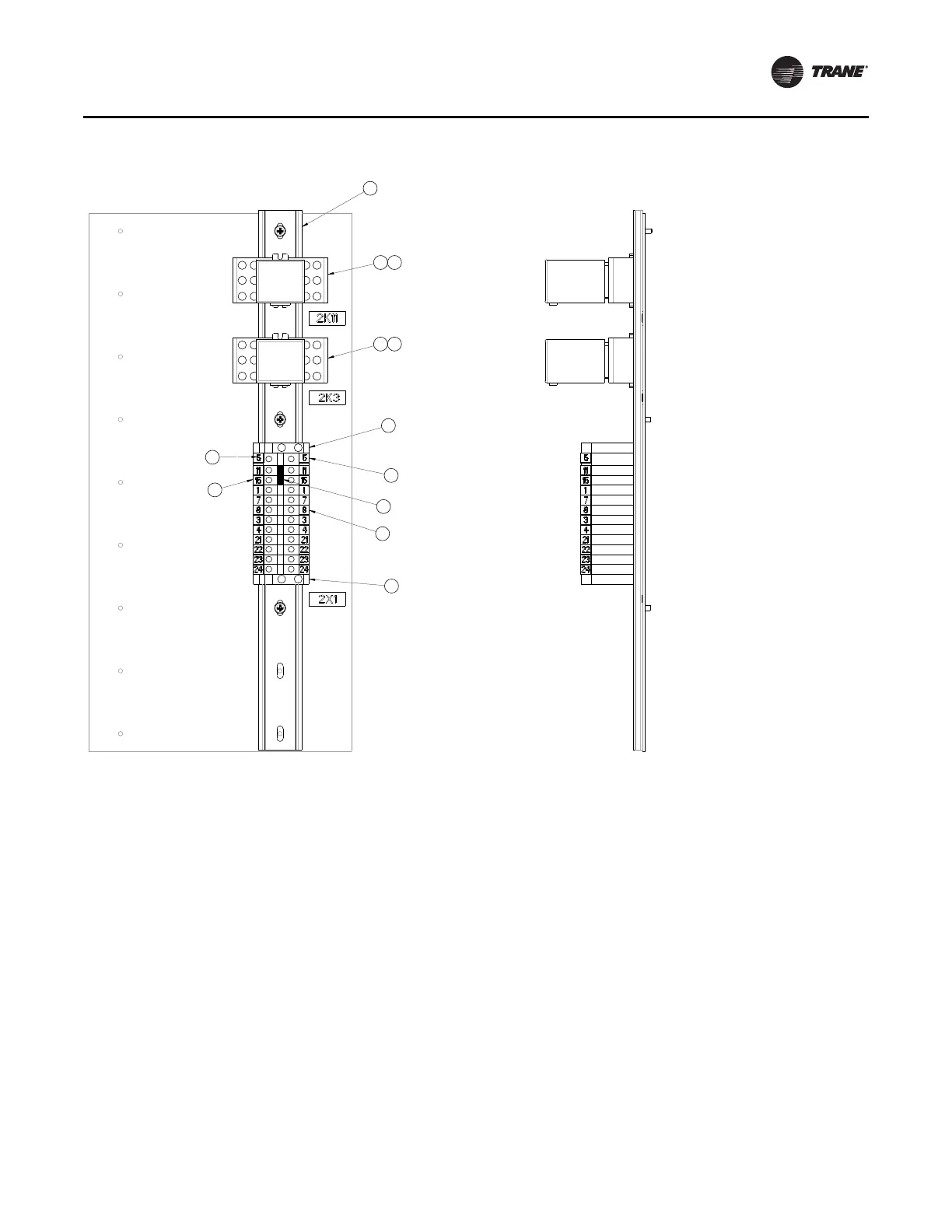
Figure 20. Expanded view of terminal block
(a)
1
2
3
4
5
6
A
B
7
8
9
1
2
3
4
5
6
A
B
7
8
9
1
23
23
4
4
5
9
6
7
8
1. Din Rail
2. Relay Socket
3. Relay
4. End Barrier
5. Ground Terminal Block
6. Terminal Block
7. Tab
8. Tab
9. Jumper
Input Power and Control Wiring
AFDK-SVU01C-EN 39
Communications wires should be terminated at the
communication card (recomm) provided on the drive. The
location of the communication card is called out as item 18
on Figure 3, p
. 12 for Frame 3 units and item 16 on
Figure 6, p. 16 for Frame 4 units. Field-installed
communica
tions wiring should be routed so that it is
segregated from all other wiring.
Refer to specific chiller documentation for exact control
panel conn
ection locations.
In remote-mount applications, the AFDK must also be
wire
d to contro
l the drive-cooling assembly. 2X1-23 and
2X1-24 provide a normally open contact. When drive
cooling is required, the contact will close and begin the
cooling system operation.
The accurate pressure readings required by the chiller
con
trols to ena
ble the most efficient operation of the
chiller with the retrofitted AFDK drive can only be
effectively measured with a pressure transducer.
A condenser pressure transducer and associated
com
mun
ications cables are included in the Valve and
Hardware kit for AFDK (020600790100). Mount the device
and connect to the IPC bus. With a laptop connected to the
chiller and with Tracer™ TU or TechView™ running, enter
the binding view menu. Highlight the device name, press
bind button, and then select the physical device with a
south pole magnet.
(a)Material courtesy of Rockwell.
 Loading...
