8 UV-PRC001-EN
Varying Coil Combinations
By varying coil combinations,
room conditions can be met using
almost any cooling or heating
source. If room requirements
change, a higher capacity coil can
be interchanged without replacing
the installed unit.
All 2-pipe and 4-piping cooling coil
assemblies come complete with a
deep insulated drain pan. A drain
pan is not provided for a heating
only system for units not contain-
ing the face and bypass option.
See Table 4 for coil types.
In a 4-pipe or couple coil situation,
main implys COOLING. Therefore,
the main coil will contain cooling,
and the auxiliary coil will contain
heating. All main coils have oppo-
Coils
site supply/return end connections
from the auxiliary coil.
In a 2-pipe coil situation, the main
coil may be either heating or cool-
ing.
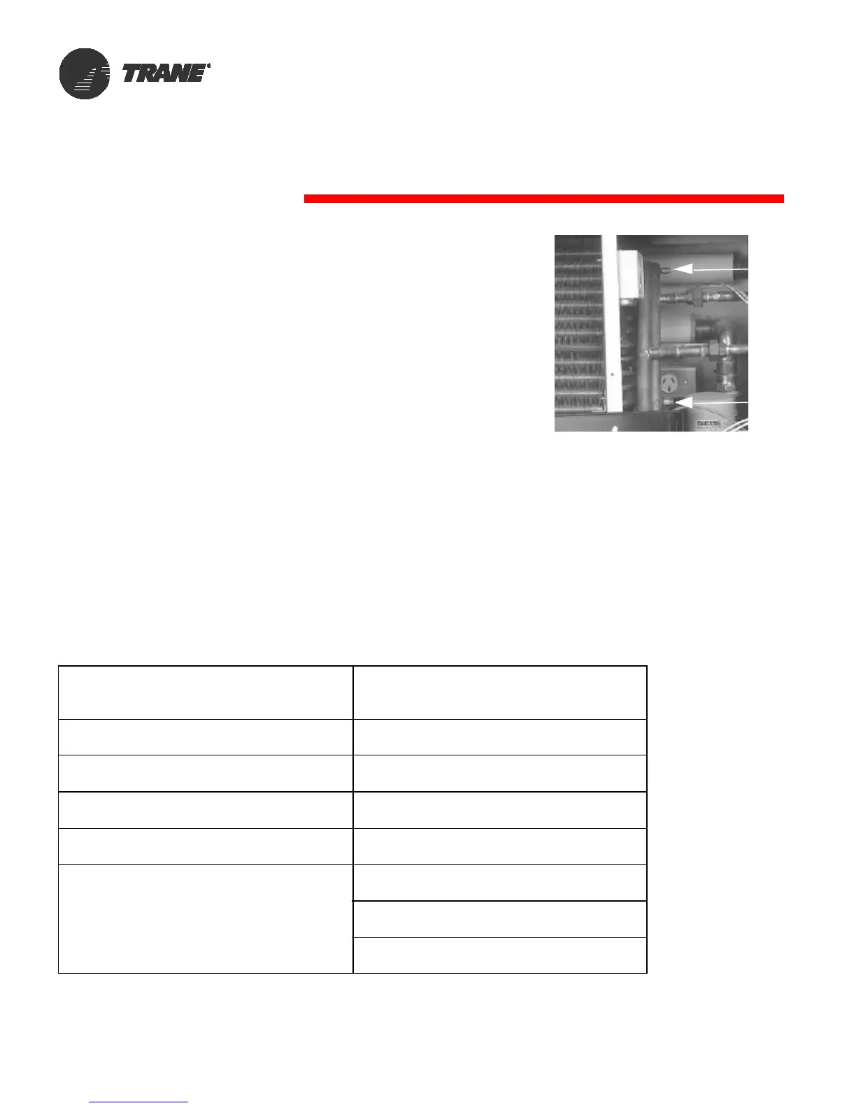
A manual air-vent is provided on
all hydronic coils. The vent allows
air to be purged from the coil dur-
ing start-up, or maintenance. The
air vent is located on the return
header of all hydronic coil sys-
tems.
Similarly, a drain plug is located at
the bottom of the MAIN coil return
header. See Figure 10 for typi-
cal header assembly.
Table 4: Coil Types
Single Coil Module Coupled Coil Module
Main/Auxiliary Coils are
opposite End Connections
AA, AB, AC, AD, AE
Combination hot water/cold water coil
DA, DC, DD, DE
Cold water/preheat hot water coil
H1, H2, H3, H4, H5, H6
Hot water ONLY coil
DK
Cold water/preheat steam coil
K1, K2
Steam ONLY coil
X3, X4, X6
Cold water/preheat electric heat coil
E4, E6, E7, E9
Electric heat ONLY coil
FA
Refrigeration/preheat hot water coil
F0
Refrigeration ONLY coil
FK
Refrigeration/preheat steam coil
F3, F4, F6
Refrigeration/preheat electric heat coil
R1, R2
Cold water/reheat hot water coil
Figure 10: Typical header
assembly
Drain
Air Vent
Plug
 Loading...