LPC-SVX01C-EN 49
4 CNT-SVX05B-EN
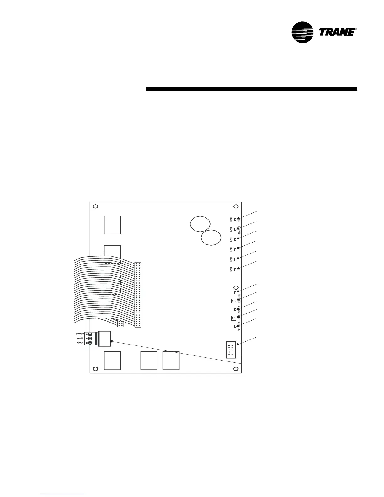
Operator-display connector
Supply fan LED (green)
Exhaust fan LED (green)
Service Pin button
Comm LED (yellow)
Status LED (green)
Test bu tto
n
DX 1 or Electric 4 LED (green)
DX 2 or Electric 3 LED (green)
DX 4 or Electric 1 LED (green
)
Service LED (red
)
Universal analog input TB43 (IN13)
DX 3 or Electric 2 LED (gre
en)
Operation
general
information
Communication with other
controllers
Tracer AH540/541 controllers operates
either in stand-alone mode or as part of a
building automation system. In either
mode of operation, multiple controllers
can be bound (bindings are configured
using the Rover service tool) to other
LonTalk®-based controllers so they can
communicate data to one another.
Figure O-GI-8. Tracer AH540/541 main controller board
Controllers that are bound as peers can
share the following data:
• Setpoint
• Zone temperature
• Zone relative humidity
• Outdoor air temperature
• Occupancy mode
• Heating/cooling mode
• Fan status
• Unit capacity control
Applications having more than one unit
serving a single space can benefit by
using this feature; it allows multiple units
to share a single space temperature
sensor and prevents multiple units from
simultaneously heating and cooling.

 Loading...


