86 LPC-SVX01C-EN
Operation
sequence of
operation
Verifying operation and
communication
This section describes:
• Test button
• How to perform a manual output test
• Service Pin button
• Light-emitting diodes (LEDs)
• Diagnostic conditions
Test button
The Test button is located on the main
controller board, as identified in Figure O-
SO-5. You can use it to perform the
manual output test, which verifies that the
controller is operating properly. The
manual output test is described in the
next section.
Performing a manual output test
The manual output test sequentially
controls all outputs to verify their wiring
and operation. Normal operation of the
controller is suspended while the manual
output test is being performed.
You can use the manual output test to
clear the controller of diagnostics. If any
diagnostics are present when a manual
test is initiated, the Status LED blinks
twice. During the second step of the test,
the controller attempts to clear the
diagnostics. If the controller cannot clear
a diagnostic, the controller exits the
manual output test.
You can also use the manual output test
for air and water balancing. Step four of
the test provides cooling capacity. Step
five provides heating capacity.
Step four also opens the outdoor air
damper to the minimum occupied
position and controls the duct static-
pressure to the duct static-pressure
setpoint.
You can perform the manual output test
in three ways:
• Press the Test button to proceed through
the test sequence
• Use the Rover service tool
• Use the operator display
To perform a manual output test using
the Test button:
1. Press and hold the Test button for 3 to 4
seconds, then release the button to
start the test mode. The green Status
LED light turns Off when the Test button
is pressed, and then it blinks (as
described in Table O-SO-18) when the
button is released to indicate the
controller is in manual test mode.
2. Press the Test button (no more than
once per second) to advance through
the test sequence.
3. Finish the test by advancing through
the complete test sequence. The test will
end automatically if the unit remains in
a single step for ten hours.
Service Pin button
The Service Pin button is located on the
main circuit board as shown in Figure O-
SO-5. You can use the Service Pin button
to:
• Identify a device
• Add a device to the active group in
Rover
• Verify communication with Rover
• Make the green Status LED “wink” to
verify the controller is communicating
on the link
Note: As an alternative to pressing the
Service Pin button, you can hold down
the zone sensor ON button for 10 seconds
to verify communication with Rover by
sending a Service Pin message request
(see “Service Pin message request”).
Refer to the
Rover Operation and
Programming
guide, EMTX-SVX01E-EN,
for information on how to use the Service
Pin button.
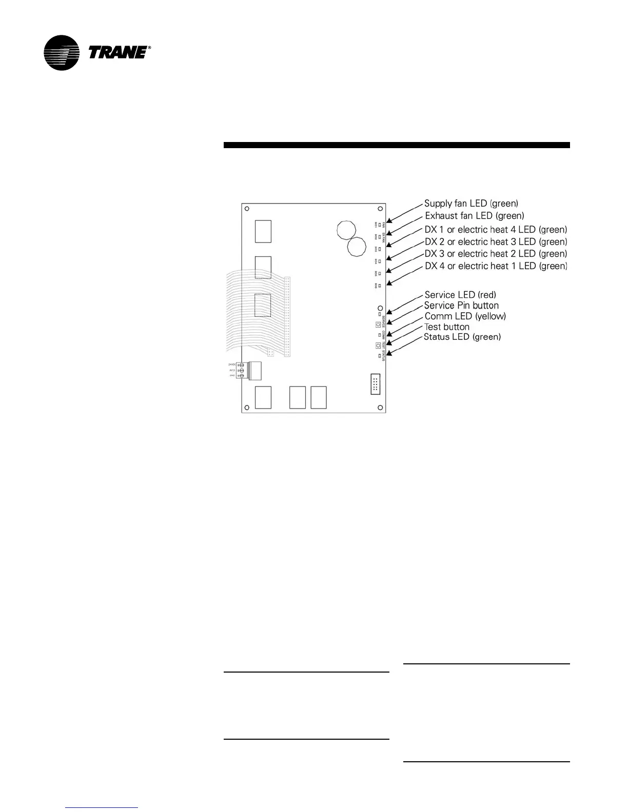
Interpreting LEDs
The information in this section will help
you interpret LED activity. The location of
each LED is shown in Figure O-SO-5.
Binary output LEDs (green)
The FAN (BO1) LED indicates the status
of the first binary output, which controls
the supply fan. The EX FAN (BO2) LED
indicates the status of the second binary
output, which controls the exhaust fan.
Binary outputs BO3, BO4, BO5, and BO6
indicate the status of stages of DX cooling
and electric heat. Table O-SO-16 describes
the LED activity for these binary outputs.
Note: Each binary output LED reflects the
status of the output relay on the circuit
board. It may or may not reflect the status
of the equipment the binary output is
controlling. Field wiring determines
whether or not the state of the binary
output LED also applies to status of the
end device. Table O-SO-16 describes the
LED states.
Figure O-SO-5. Location of Test buttons, Service Pin button, and LEDs

 Loading...


