LPC-SVX01C-EN 51
Operation
general
information
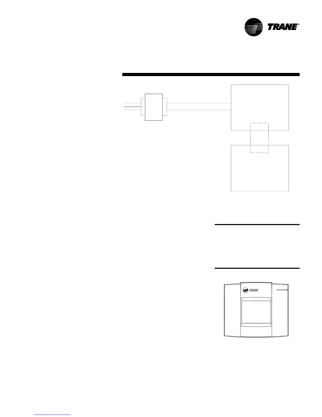
Figure O-GI-10. Power requirements
Operator display
This section explains how to install a
Tracer AH540/541 operator display and
set up the operator display.
Installing the stand-alone operator
display
With the attached cable, the stand-alone
operator display (see Figure O-GI-11)
can be mounted up to 10 ft (3 m) from the
Tracer AH541 controller. You can extend
this distance up to 150 ft (46 m) using
four-conductor wire and the included pig-
tail connectors. Alternately, use three
twisted-pair wires. Trane recommends
the following four-conductor wires:
• Plenum 18 AWG, Trane part number
400-2059
• Plenum 22 AWG, Trane part number
400-2020
• Non-plenum, Trane part number 400-
1005
Figure O-GI-11. Tracer AH541 stand-alone
operator display
CAUTION
Avoid
Equipment Damage!
To
clean the operator display, use a cloth
dampened with commercial liquid
glass cleaner. Spraying water or
cleansers directly on the screen may
result in equipment damage.
Termination board
Main controller board
Transformer
Line
voltage
24 Vac

 Loading...


