78 RLC-SVX07A-EN
Installation - Electrical
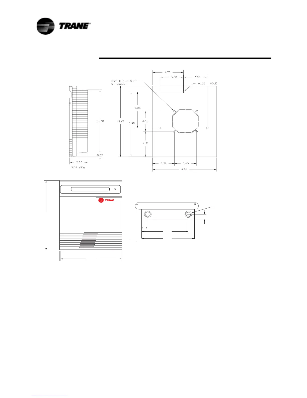
Remote CLD Mounting
All mounting hardware (tools, screws, etc.) is to be field supplied. Figure 32
shows the mounting holes in the back of the Remote CLD panel. Also shown
are the electrical access knockouts at the bottom and top of the panel.
Remove the knockouts that will be used for wire entry, prior to mounting the
panel.
NOTE: On the back of the panel is a knockout for an electrical outlet box, if
one is to be used.
Prior to mounting the panel, the actual keypad board needs to be swung
open. To swing the keypad board our of the way, remove the two screws on
the right side of the keypad. With the screws removed, the keypad board can
be swung to the left, to obtain access to the mounting holes.
Attach the display box to the mounting surface with screws through the
mounting hole and two mounting slots, show in Figure 32.
Figure 32 Remote CLD Panel Mounting Holes and Electrical Access Knockouts
+./#+/543
/.4/0/."/44/-
-/5.4).'0!44%2.
&2/.46)%7
 Loading...


