RLC-SVX07A-EN 85
Operating Principles
Refrigeration (Cooling) Cycle
RTWA Cycle Description
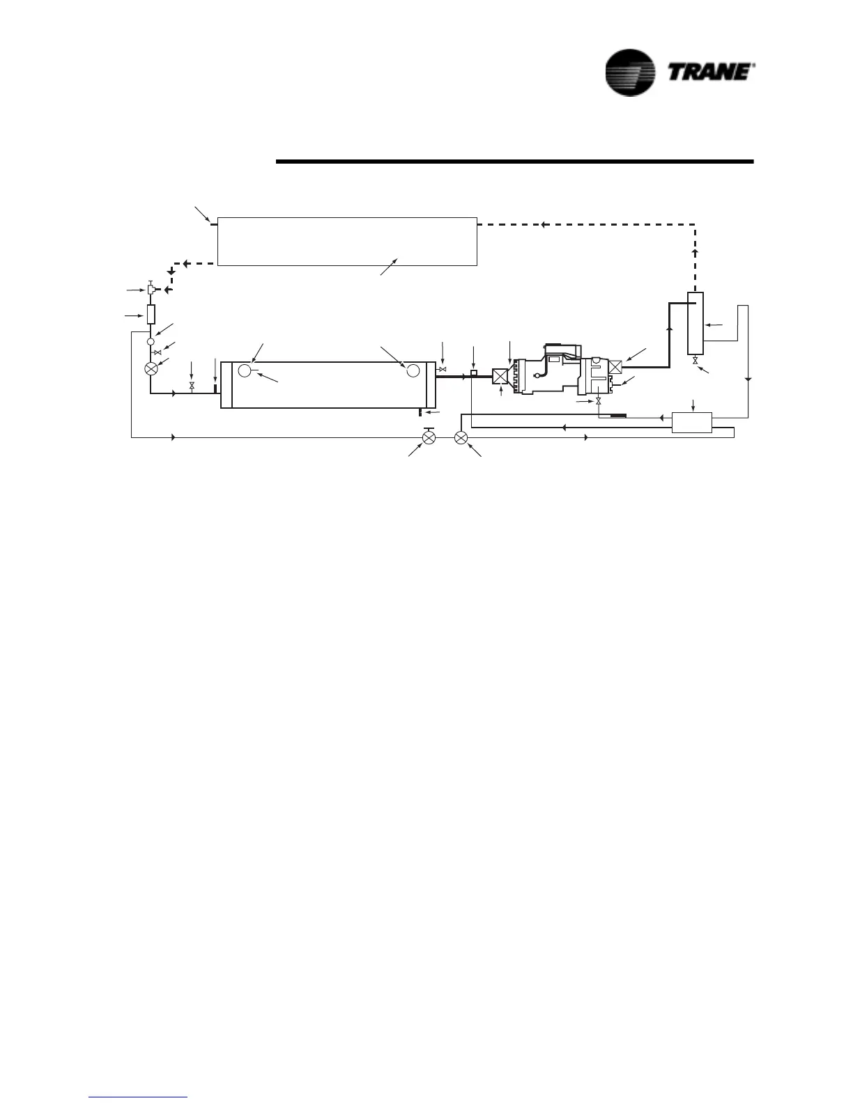
Figure 35 represents the refrigeration system and control components of an
RTWA. Vaporized refrigerant leaves the evaporator and is drawn into the
compressor. Here it is compressed and leaves the compressor as a mixture
of hot gas and oil (which was injected during the compression cycle).
The mixture enters the oil separator at the in/out cap. The separated oil flows
to the bottom of the separator, while the refrigerant gas flows out the top and
passes on to the tubes in the condenser. Water flows through the copper
tubes in the condenser, which removes the heat from the refrigerant and
condenses it.
The condensed refrigerant passes through the electronic expansion valve and
into the tubes of the evaporator. As the refrigerant vaporizes, it cools the
system water that surrounds the tubes in the evaporator.
Figure 36 RTUA with RTCA Refrigeration System and Control Components
7
3
1
14
13
12
8
RTCA
Condenser
Evaporator
5
4
2
6
24
23
22
21
19
9
18
16
15
17
20
11
10
1. Discharge Service Valve 10. Liquid Line Service Valve 19. Temperature Responsive Valve
2. Oil Separator (Backseat Port Upstream) 20. Entering Water Connection
3. 1/4” Angle Valve 11. Filter/Dryer 21. Evaporator Entering Water
4. Oil Cooler (if “V” is in 17th digit 12. Sight Glass Temperature Sensor
of Model #) 13. Schrader Valve 22. Relief Valve
5. Oil Line Service Valve 14. Electronic Expansion Valve 23. Suction Service Valve
6. Oil Temperature Sensor 15. 1/4” Angle Valve 24. Compressor Suction Refrigerant
7. Condenser 16. Saturated Condenser Temperature Sensor
8. Saturated Condenser Refrigerant Temperature Sensor 25. Low Pressure Switch
Refrigerant Temperature Sensor 17. Leaving Water Connection
9. Solenoid Valve 18. Evaporator Leaving Water
Temperature Sensor
NOTE: - - - Field Installed Piping
_____
Factory Installed Piping
 Loading...


