86 RLC-SVX07A-EN
Operating Principles
RTUA With RTCA Cycle Description
Figure 36 represents the refrigeration system and control components in a
system comprised of an RTUA and an RTCA. Vaporized refrigerant leaves the
evaporator and is drawn into the compressor. Here it is compressed and
leaves the compressor as a mixture of hot gas and oil (which was injected
during the compression cycle).
The mixture enters the oil separator at the in/out cap. The separated oil flows
to the bottom of the separator, while the refrigerant gas flows out the top and
passes through the tubes in the condenser. Air flows over the coils in the
condenser, which remove the heat from the refrigerant and condenses it.
The condensed refrigerant passes through the electronic expansion valve and
into the tubes of the evaporator. As the refrigerant vaporizes, it cools the
system water that surrounds the tubes in the evaporator.
Compressor Description
The compressors used by the Model RTWA and RTUA Series “R” Water-
cooled chiller consists of two distinct components: the motor and the rotors.
Compressor Motor
A two-pole, hermetic, squirrel-cage induction motor (3600 rpm) directly drives
the compressor rotors. The motor is cooled by suction refrigerant gas from
the evaporator, entering the end of the motor housing through the suction
line.
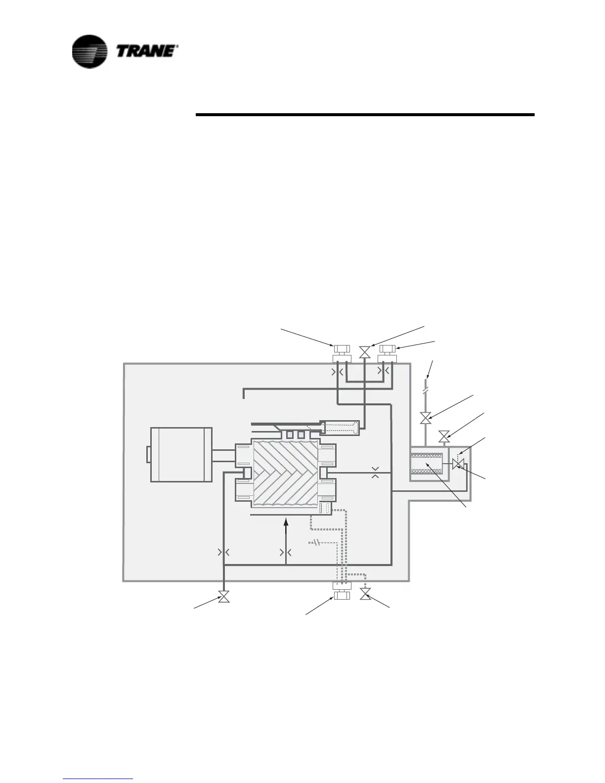
Figure 37 RTWA Refrigerant and Oil Diagram
6FKUDGHU
9DOYH
6FKUDGHU
9DOYH
6FKUDGHU9DOYH
6FKUDGHU
9DOYH
)HPDOH
8QORDGHU
6ROHQRLG9DOYH
0DVWHU
2LO9DOYH
'LVFKDUJH
3UHVVXUH
,QWHJUDWHG
2LO)LOWHU
4XLFN&RQQHFW6KXWRII
9DOYHRU$QJOH9DOYH
)URP2LO&RROHU
0DOH8QORDG
6ROHQRLG9DOYH
0DOH/RDG
6ROHQRLG
9DOYH
0DOH
)HPDOH
0RWRU
6XFWLRQ
6XFWLRQ
6XFWLRQ
7R5RWRU
2LO,QVSHFWLRQ
'LVFKDUJH
3UHVVXUH
 Loading...


