57
RTAA-IOM-3
Installation –
Electrical
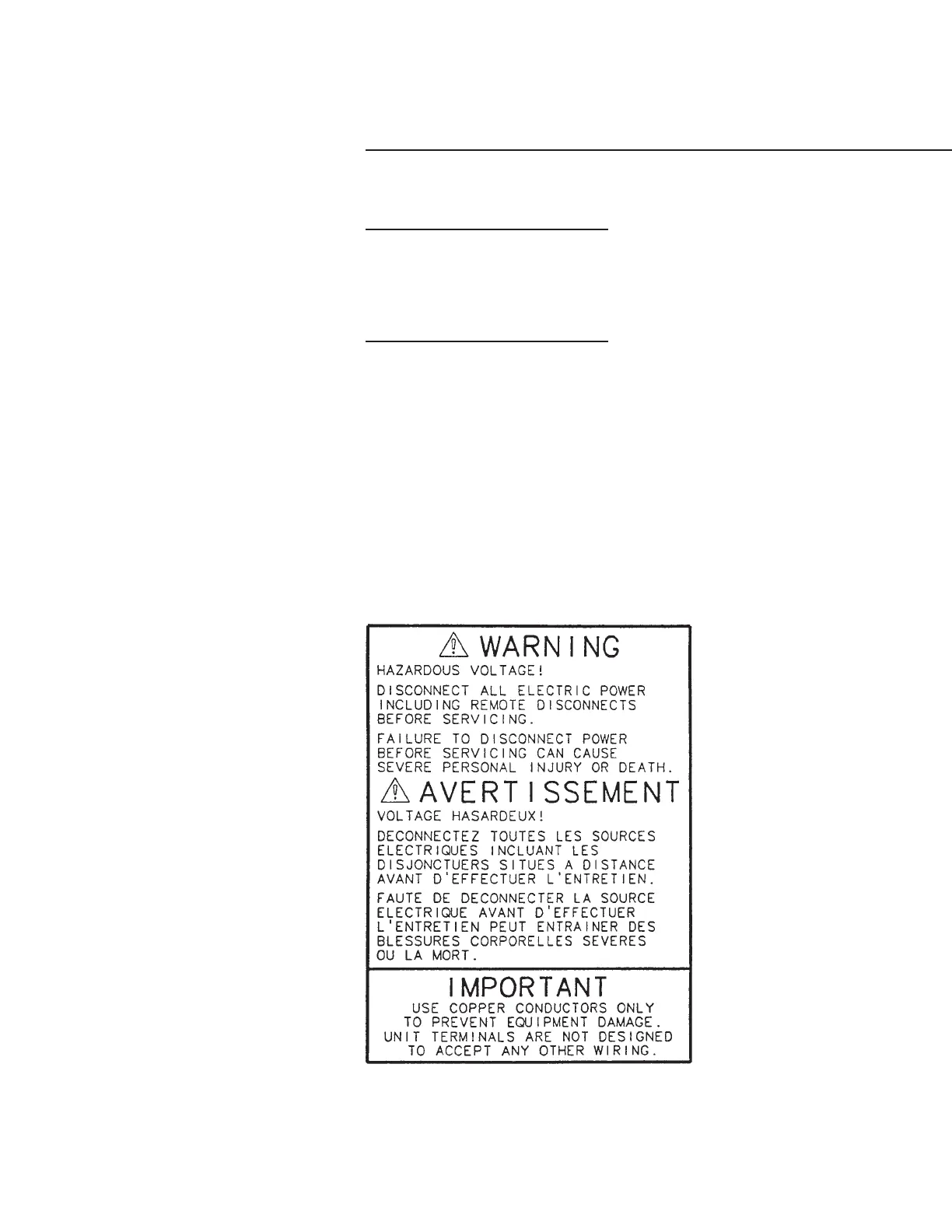
Figure 33
Warning Label
General
Recommendations
WARNING: The Warning Label
shown in Figure 33 is displayed
on the equipment and shown on
wiring diagrams and schematics.
Strict adherence to these
warnings must be observed.
All wiring must comply with local
codes and the National Electric Code.
Typical field wiring diagrams are
shown in Figures 34 thru 36. Minimum
circuit ampacities and other unit
electrical data are on the unit
nameplate and are shown in Table 10.
See the unit order specifications for
actual electrical data. Specific electrical
schematics and connection diagrams
are shipped with the unit.
Caution: To avoid corrosion and
overheating at terminal
connections, use copper
conductors only.
Do not allow conduit to interfere with
other components, structural members
or equipment.
Control voltage (115V) wiring in
conduit must be separate from conduit
carrying low voltage (<30V) wiring.
Caution: To prevent control
malfunctions, do not run low
voltage wiring (<30V) in conduit
with conductors carrying more
than 30 volts.
 Loading...


