28
RTAC-SVX005A-EN
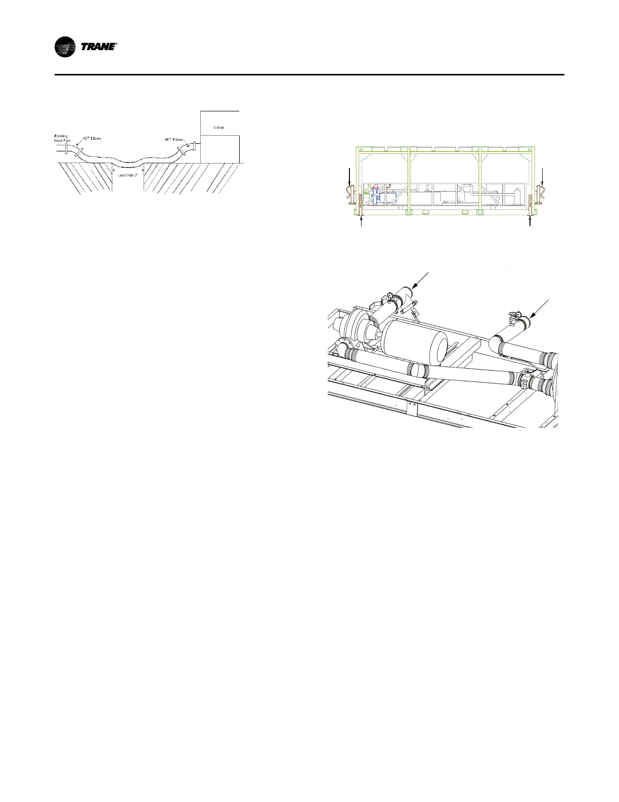
Figure 25. Correct unsupported horizontal
installation
Figure above illustrates a correct horizontal hose
installation where there is a section of unsupported hose.
The length of unsupported hose should be less than 7 feet.
The hose must be adequately supported by having more
than half its total length on the ground.
Hard Pipe Guidelines
Certain installations may require the use of hard pipe (steel
or PVC). Hard pipe is typically recommended for semi-
permanent installations (three months or more),
installations with space limitations and/or between
connection and pump inlet.
When installing hard pipe:
• Construct and install the piping according to local and
national codes.
• Isolate and support the piping as required to prevent
stress on the unit and vibration to building piping.
If there are any questions regarding how to install water
piping, contact Trane Rental Services.
Exceptions
Trane Rental Services Engineering must authorize any
exceptions to the guidelines established in this bulletin in
writing.
Material Disposition
In the event the hose fails or leaks, contact Trane Rental
Services, tag the hose “BAD”, and place it in the shipping
box.
Leveling System
Each Trane Rental Services RTAC unit must be level to 1/4
inch over the length of the chiller. Level the chiller using
four manual jacks with attachments points located on the
corners of the lifting frame (155 to 250 ton) or trailer (300 to
500 ton).
F2-F4 style RTAC chillers ship with jacks that will need to
be relocated from the shipping position to the installation
position as shown in Figure 26, p. 28. 300 to 500 ton
chillers will require the two rear jacks to be removed from
the trailer mounted box and installed prior to startup. If 155
to 250 ton chillers are commissioned on trailers, ensure the
trailer is level. Do not use the jacks mounted to the chiller.
During decommissioning, return jacks to the shipping
position.
Figure 26. F2-F3 RTAC jack positions
Shipping
Position
Operating Position
Operating Position
Shipping
Position
Figure 27. Water inlet/outlet connections
Notes:
• The water inlet and outlet connections are both
6 inch Victaulic.
• Water pipes should be routed away from the
compressor access panels to allow for
compressor servicing or replacement.
Freeze Protection
A glycol type anti-freeze may be required for freeze
protection. For more information, reference RTAC Freeze
Avoidance section in RF-PRB002*-EN.
Flow Sensor
An electronic flow sensor is installed on this RTAC unit near
the outlet piping. This flow sensor is wired into the controls
of this RTAC unit. The RTAC unit has a pump interlock
control that requires flow to operate. If there is no flow
through the evaporator of the RTAC unit, the chiller will not
start or will shut down if the evaporator looses flow. Refer
to the Chilled Water Flow (Pump) Interlock section of
RTAC-SVX01*-EN for chilled water flow information.
Installation - Mechanical
 Loading...


