RTAC-SVX005A-EN
33
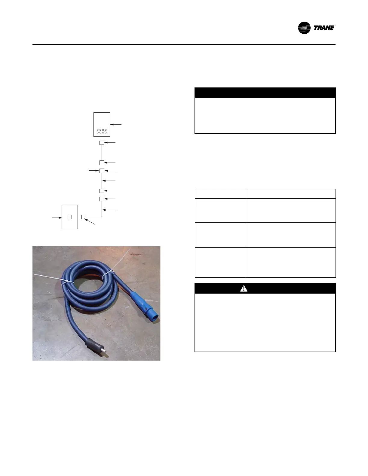
Pigtail
Each cable box has pigtails for non cam-type connections.
There is a cam-type on one end and a barrel lug on the
other. The barrel lug end allows for connection into a power
distribution panel or non cam-type equipment. The pigtail
can be connected to the standard cam-type cable, see
Figure 33, p. 33.
Figure 33. Electrical connector overview
Directly to Unit
or Second Pigtail
Customer
Breaker
Lug
7 ft. Pigtail
Cam
Cam
100 ft. 2/0 or 4/0
with camloks on each end
Cam
Cam
Lug
Shore Power Enclosure
Figure 34. Pigtail
Field Installed Power Wiring
An overall dimensional layout for the field installed wiring
entrance into the unit is illustrated in Figure 1, p. 9 to
Figure 17, p. 25. To ensure that the unit's supply power
wiring is properly sized and installed, follow the guidelines
outlined below.
Note: All field installed wiring must conform to NEC
guidelines as well as State and Local codes.
Verify power supply available is compatible with the unit
nameplate. The available supply power must be within 10%
of the rated voltage stamped on the nameplate. Use only
copper conductors to connect the three-phase power
supply to the unit.
NOTICE
Use Copper Conductors Only!
Failure to use copper conductors could result in
equipment damage as the equipment was not
designed or qualified to accept other types of
conductors.
Circuit Breaker External Handle - Factory
Mounted Option
Units have an external mounted circuit breaker handle. The
operator can disconnect power from the unit without
opening the control panel door. See the following table for
locations and positions.
Position Locations
ON
• Circuit breaker is closed.
• Main power supply to be applied at the
unit.
OFF
• Circuit breaker is open.
• Main power supply to the unit is
interrupted.
OPEN/COVER/RESET
• Turn the handle to release the handle
from the circuit breaker.
• The control panel door can now be
opened.
WARNING
Hazardous Voltage!
Failure to disconnect power before servicing could
result in death or serious injury.
Disconnect all electric power, including remote
disconnects before servicing. Follow proper lockout/
tagout procedures to ensure the power can not be
inadvertently energized. Verify that no power is
present with a voltmeter.
Once the door is open, it can be closed with the handle in
any one of the three positions outlined above. Match the
circuit breaker position.
For specific electrical schematic and connection
information, refer to the ship-with wiring diagram.
Main Unit Power Wiring
The electrical service must be protected from over current
and short circuit conditions in accordance with NEC
requirements. Protection devices must be sized per the
NEC according to the electrical data on the nameplate.
Installation - Electrical
 Loading...


