RTAC-SVX005A-EN
29
Installation - Electrical
Electrical Connections
WARNING
Proper Field Wiring and Grounding
Required!
Failure to follow code could result in death or serious
injury.
All field wiring MUST be performed by qualified
personnel. Improperly installed and grounded field
wiring poses FIRE and ELECTROCUTION hazards. To
avoid these hazards, you MUST follow requirements
for field wiring installation and grounding as
described in NEC and your local/state/national
electrical codes.
Depending on style, RTAC Rental chillers can accept main
incoming power in the methods listed in Table 2, p. 29. It is
recommended that cable be laid out starting from the chiller
working back to the electrical distribution panel. Confirm
cam connection types mate with the chiller properly.
Table 2. Rental RTAC electrical connections
Chiller Sequence Connection Style Available
F0
Series 16 Cam-type Connections
Terminal Lug Connections (accepts up to 600
MCM Wire)
F2-F4
Series 16 Cam-type Connections Only
300 and 400 Ton Electrical Connections
The F0-style 300 and 400 ton RTAC Rental chillers are
configurable for single or dual point power. Units will ship in
the dual point power configuration. These chillers have
separate nameplates detailing electrical requirements for
each configuration.
See the labeled instructions on the single point power
enclosure for the detailed procedure explaining how to
configure the unit for single or dual point power. If
instructions are missing or unclear, contact Trane Rental
Services.
Note: The jumper bars should always be checked for the
proper configuration before power is supplied to the
unit.
Installation of Jumper Bars for Single
Point Power
The jumper bars are bolted tightly into position as shown in
Figure 28, p. 29, with the hardware supplied. When the
jumper bars are connected for each phase, the unit is
configured for single point power. When the jumper bars
are not connected for each phase, the unit is configured for
dual point power.
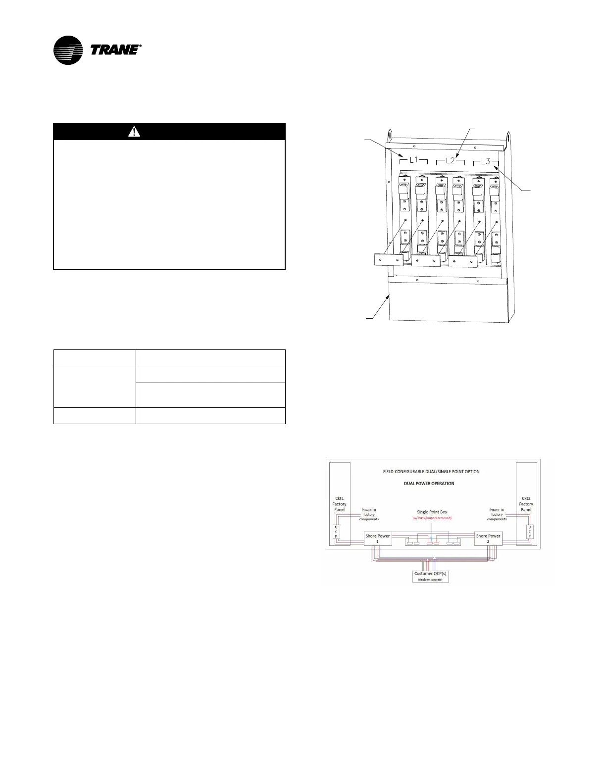
Figure 28. Single point power enclosure
Leg 1
Leg 2
Leg 3
Jumpers Bars
(One Bar for
Each Leg)
Note: Always use rental nameplate data to size wire to this
unit.
Dual Point Power
Field wiring must be connected to the cam-type enclosures
for either cam-type connections or for hard wiring. Jumper
bars must not be connected.
Figure 29. Dual point configuration
Single Point Power
Field wiring must be connected to the single point power
enclosure only. Cam-type boxes must not be used for the
single point power configuration. Cam-type connectors
may not be used.
Remove the plate cover from the single point power
enclosure and terminate the connections from the building
circuit breaker inside the cam-type enclosure. Jumper bars
must be connected for each leg.