RLC-SVX14H-GB
60
Installation – Electrical
Control Power Supply
The unit is equipped with a control power transformer;
it is not necessary to provide additional control power
voltage to the unit. All units are factory-connected for
appropriate labeled voltages.
Interconnecting Wiring
Chilled Water Flow (Pump) Interlock
The Model RTWD Series R
®
chiller requires a fi eld-
supplied control voltage contact input through a fl ow
proving switch 5S5 and an auxiliary contact 5K9 AUX.
Connect the proving switch and auxiliary contact to
1A15 J3-1 and 1X4-1. Refer to the fi eld wiring for details.
The auxiliary contact can be starter contactor auxiliary.
or any signal which indicates the pump is running.
A fl ow switch is still required and cannot be omitted.
Chilled Water Pump Control
An evaporator water pump output relay closes when
the chiller is given a signal to go into the Auto mode
of operation from any source. The contact is opened to
turn off the pump in the event of most machine level
diagnostics to prevent the build up of pump heat.
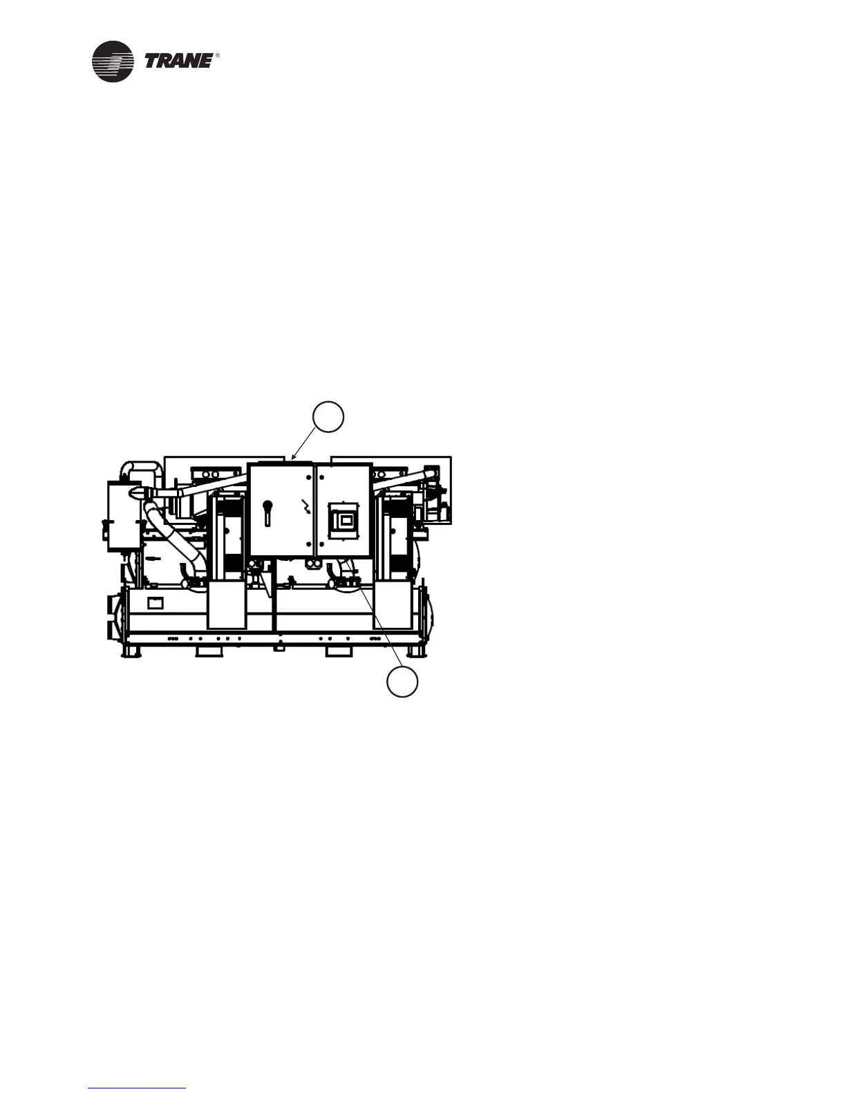
A = Incoming power entrance
B = Low voltage entrance
Figure 11 - Power Entrance
A
B
 Loading...