RLC-SVX14H-GB
75
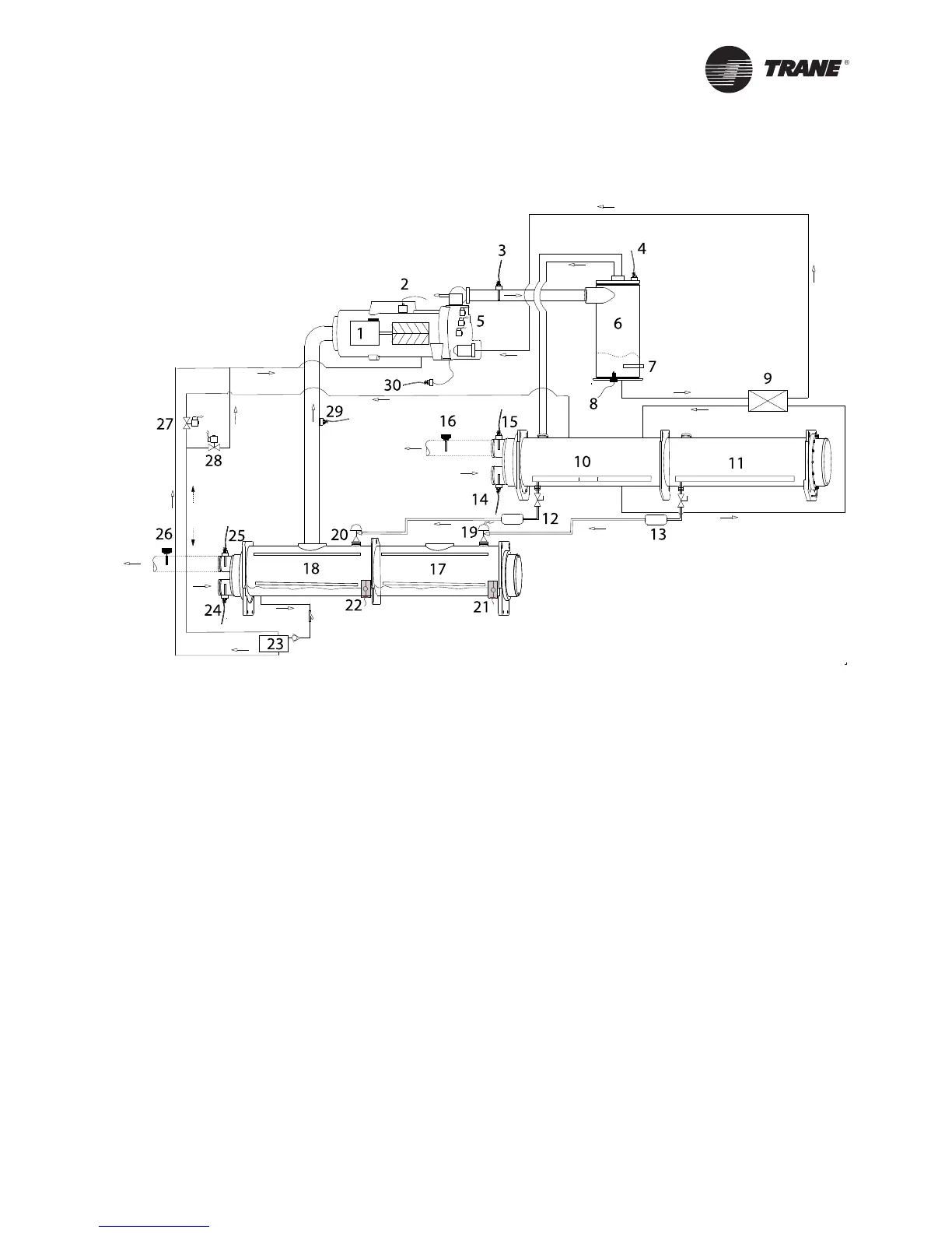
Figure 16 - RTWD/RTUD Typical Refrigerant Circuit
1 Compressor A - circuit 1
2 High Pressure Cutout Switch
3 Comp. Discharge Temp Sensor
4 Cond. Rfgt. Pressure Trans.
5 Load/Unload and Step Solenoids
6 Oil Separator Circuit 1
7 Oil Heater
8 Optical Oil Loss Level Sensor
9 Oil Cooler (optional for RTWD)
10 Condenser - circuit 1 (RTWD only)
11 Condenser - circuit 2 (RTWD only)
12 Refrigerant Filter - circuit 1
13 Refrigerant Filter - circuit 2
14 Condenser Enter Water Temp. Sensor (RTWD only)
15 Condenser Leaving Water Temp. Sensor (RTWD only)
16 Condenser Water Flow Switch (RTWD only)
17 Evaporator - circuit 2
18 Evaporator - circuit 1
19 EXV - circuit 2
20 EXV - circuit 1
21 Liquid Level Sensor -circuit 2
22 Liquid Level Sensor -circuit 1
23 Gas Pump - circuit 1
24 Evaporator Entering Water Temperature Sensor
25 Evaporator Leaving Water Temperature Sensor
26 Evaporator Water Flow Switch
27 Gas Pump Drain Solenoid Valve
28 Gas Pump Fill Solenoid Valves
29 Suction Pressure Transducer
30 Oil Pressure Transducer
Note : The schematic above is typical refrigerant fl ow
diagram. For accurate fl ow chart refer to relevant fl ow
diagram shipped with the unit
Operating Principles
 Loading...