12
BAS-SVX48H-EN
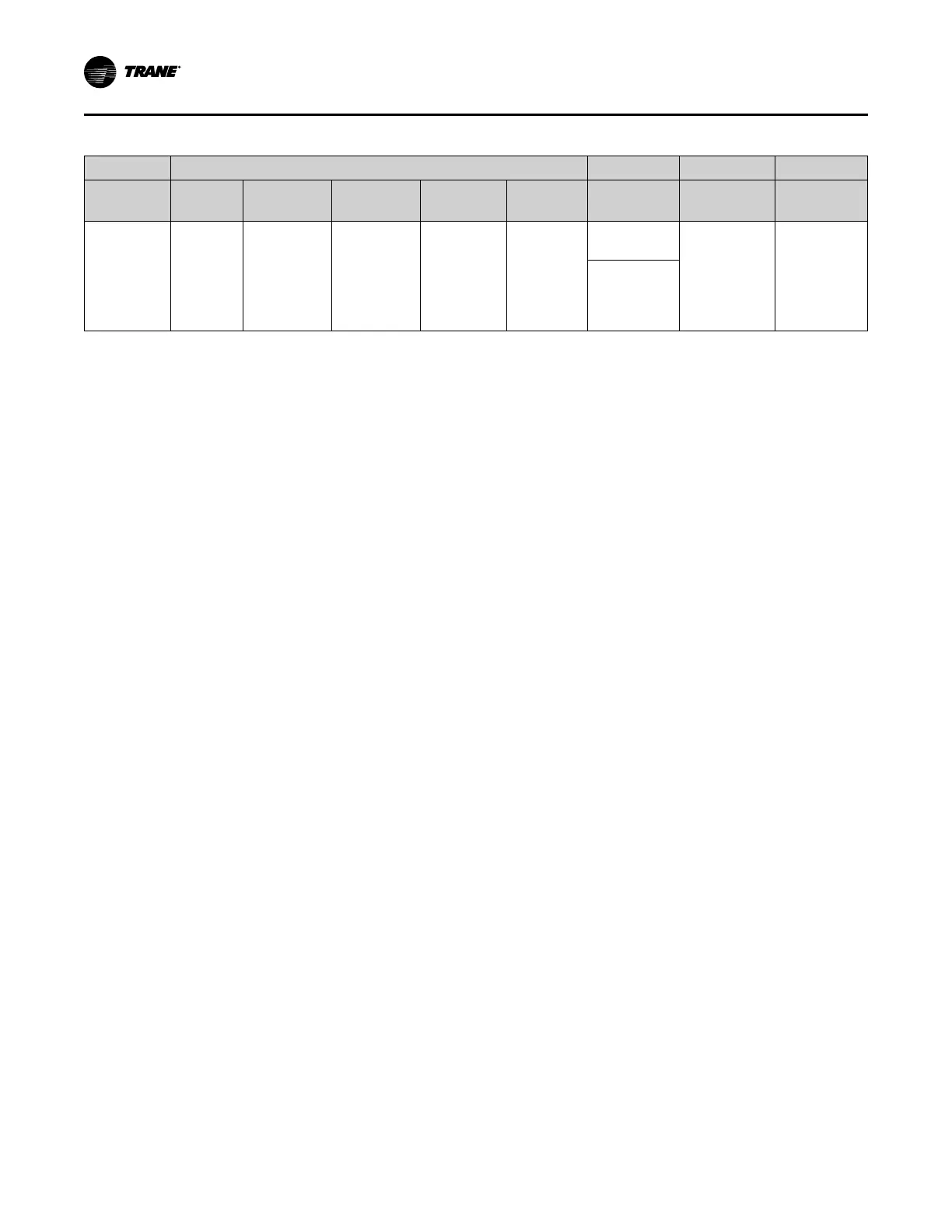
Table 3. UC400 Controller Supported Sensors and Features (continued)
Features
Sensor
Type
Setpoint
Fan
Control
System Occupancy
LEDs
Part
Number
BAYSENS
Global
Parts
Wireless
Zone Sensor
w/Fan
Control
Single
• Off
• Auto
• Low
• Medium
• High
No Yes No
X1379082201
(Sensor Only)
N/A N/A
X1379082401
(Sensor Set)
(a)
This sensor can be field configured to match the applicable unit controller options. Unit controller inputs for system status, fan, and service required are
not available on this sensor. If replacing a BAYSENS031A or a BAYSENS035A sensor, and status indicators are required, replace with non-display sensor
BAYSENS109A or BAYSENS110A.
Valve and Damper Actuators
The 2-position analog and 3-wire floating point modulating actuators cannot exceed 12 VA draw
at 24 Vac. For 2-position valves, use actuators with ON/OFF and spring actions that returns the
valve to normally open (NO) or closed (NC), which are dependent on the desired default position.
For modulating actuators, use actuators with or without a spring return, as required by the
application.
Zone Humidity Sensor
For measurement of relative humidity (RH), the UC400 Controller requires a zone humidity
sensor with a 4–20 mA output, where 4 mA is 0% RH and 20 mA is 100% RH. The controller
provides 24 Vdc to power the zone humidity sensor.
NNoottee:: As an option, the UC400 Controller can receive humidity from a Trane Air-fi™ Wireless
Sensor with Humidity.
CO
2
Sensor
The UC400 Controller assumes (by default) that the CO
2
sensor provides a 4-20 mA output when
measuring carbon dioxide (CO
2
). The controller provides 24 Vdc to power the CO
2
sensor.
Expansion Modules
The UC400 Controller can power a maximum of two (2) DC expansion modules (either the Tracer
XM30 or Tracer XM32) without an additional power supply. It can support a maximum of 32
additional XM30, XM32 or XM70 hardware terminations when properly applying power.
AAddddiittiioonnaall CCoommppoonneennttss

 Loading...


