32
BAS-SVX48H-EN
Table 7. BACnet Device ID Calculations (continued)
Unit Controller MAC Address (38)
0 3 8
BACnet Device ID: 211038 0 2 1 1 0 3 8
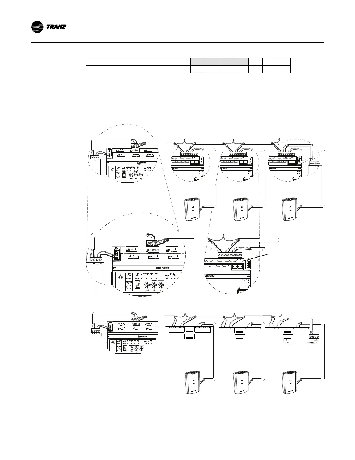
BACnet MS/TP Link Wiring
The wire must be low-capacitance, 18-gauge, stranded, tinned-copper, shielded, twisted-pair.
The illustration below shows an example of BACnet link wiring with multiple UC400 Controller
controllers.
Figure 14. BACnet MS/TP Link Wiring for UC400 and UC400-B
BI LINK IMC
+
VDC
AI
AIAI AI AI
P P
TX
RX
LINK IM
SERVI
SERVICE TOOL
IM
BI LINK IMC
+
VDC
AI
AIAI AI AI
P P
TX
RX
LINK IM
SERVI
SERVICE TOOL
IM
BI LINK IMC
+
VDC
AI
AIAI AI AI
P P
TX
RX
LINK IM
SERVI
SERVICE TOOL
IM
+
+
BI LINK IMC
+
VDC
AI
AIAI AI AI
P P
TX
RX
LINK IM
SERVI
SERVICE TOOL
IM
+
BI LINK IMC
+
VDC
AI
AIAI AI AI
P P
TX
RX
LINK IM
SERVI
SERVICE TOOL
IM
+
UC400 UC400 UC400
Zone
Sensor
Zone
Sensor
Zone
Sensor
Zone Sensor
Communications
Jack Wiring
Tracer SC
Trane BACnet Terminator
+
+
24VDC
GND
Comm +
Comm -
BACnet
+ - + -
IMC
+
-
G
n
d
2
4VDC
1
2
34
1
23
4
1
2 3
4
1
2 3
4
24VDC
GND
Comm +
Comm -
BACnet
+ -
+ -
IMC
+
-
G
n
d
2
4VDC
1
2
34
1
23
4
1
2 3
4
1
2 3
4
24VDC
GND
Comm +
Comm -
BACnet
+ -
+ -
IMC
+
-
Gnd24
VDC
1
2
34
1
23
4
1
2 3
4
1
2 3
4
Tracer SC UC400-B
Zone Sensor
Trane
BACnet
Terminator
Zone Sensor Zone Sensor
UC400-B UC400-B
WWiirriinngg IInnssttaallllaattiioonn

 Loading...


