44
BAS-SVX48H-EN
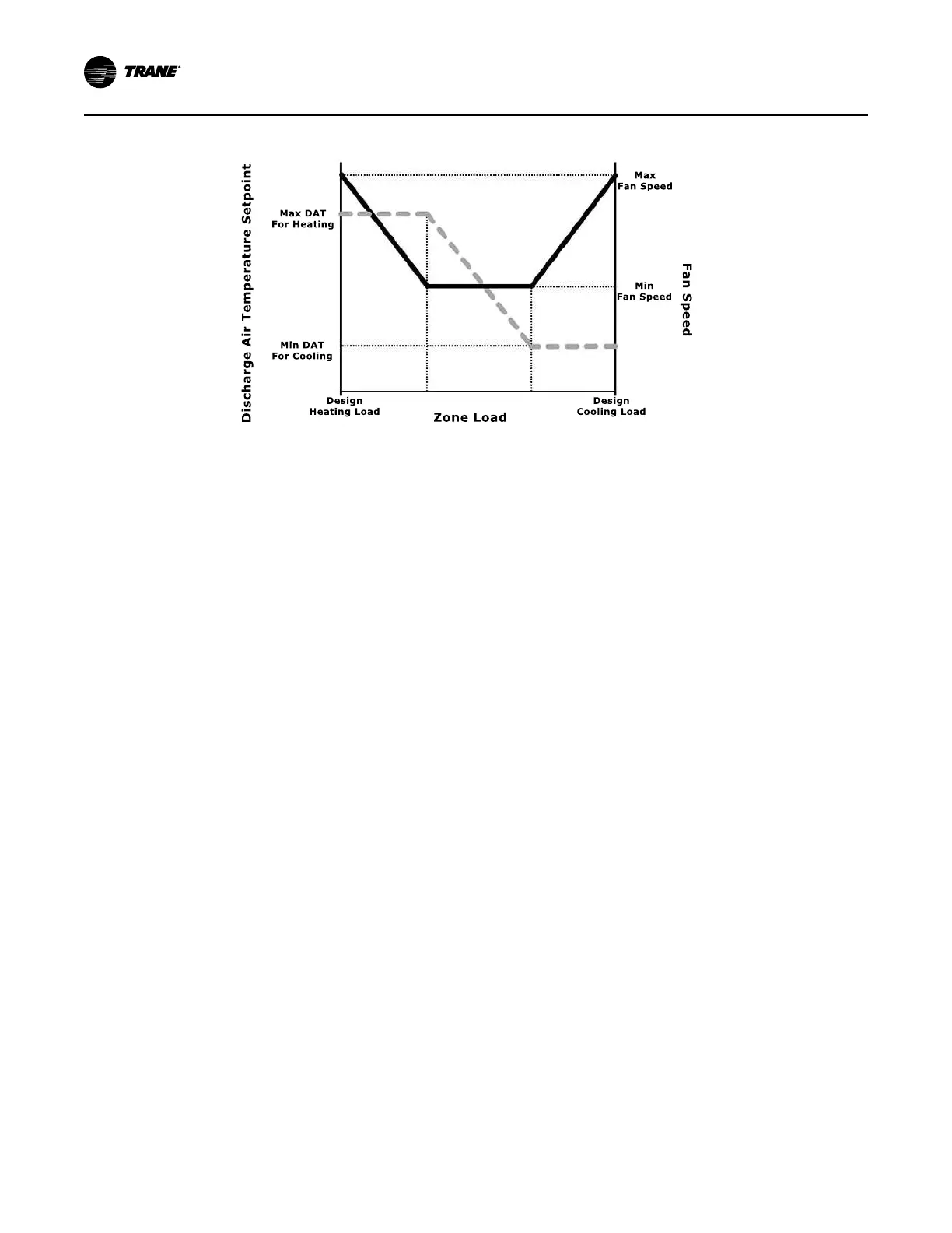
Figure 19. Cooling/Heating Load Changes
At high heating loads, the fan speed modulates to maintain the zone temperature at heating
setpoint, while the heating capacity modulates or stages to maintain the DAT at the maximum
limit. At lower heating loads, the fan operates at minimum speed, while heating capacity
modulates or stages to maintain the zone temperature at heating setpoint.
• EECCMM EEnneerrggyy EEffffiicciieennccyy MMooddee:: when the UC400 Controller is configured for Energy Efficient
Mode by means of the Fan Operating Mode Request MV point, the controller and daughter
board minimizes energy use by running the fan at the lowest possible speed while
maintaining space temperature. The controller fully utilizes valves, economizer, or electric
heat which increases fan speed to meet space temperature (unless the fan has been manually
controlled.
• EECCMM AAccoouussttiiccaall MMooddee:: when the UC400 Controller is configured for Acoustical Mode by
means of the Fan Operating Mode Request MV point, the controller and daughter board
minimizes acoustical nuisance by balancing changes in fan speed and total fan noise. The
controller fully opens the cooling and heating valves before increasing fan speed to meet
space temperature unless the fan has been manually controlled. If multiple stages of electric
heat exist, the controller uses a single minimum air flow for each stage.
Exhaust Control
Exhaust control is achieved by a single-speed exhaust fan and controlled by binary output 2
(BO2). Exhaust control, if not present, can be enabled by selecting YYeess under the Exhaust Fan
Selection on the Tracer TU Configuration page under the Equipment Options group.
NNoottee:: Exhaust fan configuration cannot be selected with 3-speed fan operation.
IImmppoorrttaanntt:: If exhaust control is added to an existing configuration, all other configuration
options should be verified to match the correct equipment options. Temperature and
flow setpoints revert to default values.
The exhaust function is coordinated with the supply fan and outdoor/return air dampers as
follows:
• The exhaust fan energizes when the fan is running and when the outdoor air damper position
is greater than or equal (≥) to the exhaust fan enable position (or the outside air damper
position at which the exhaust fan turns ON)..
• The exhaust fan turns OFF when the fan either turns OFF or the outdoor air damper closes to
10% below the exhaust fan enable position.
• If the exhaust fan/damper enable setpoint is less than 10%, the exhaust output is energized if
the outdoor air damper position is at the setpoint and de-energized at 0.
SSeeqquueennccee ooff OOppeerraattiioonn

 Loading...


