14
BAS-SVX46E-EN
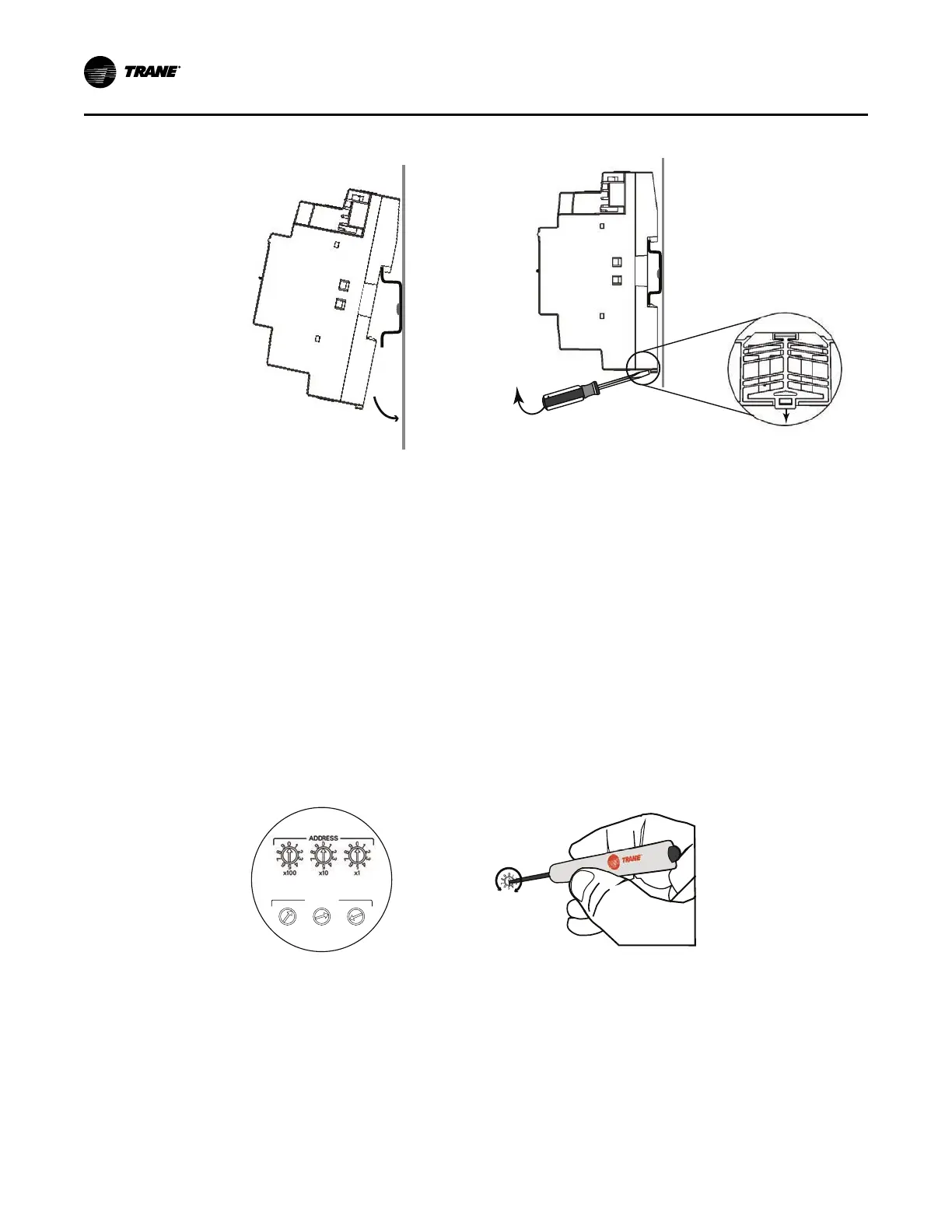
Figure 4. Mounting and removing the device
Slotted release clip
shown from back side
Mounting
Removing
Setting Rotary Switch Addresses
All Tracer expansion modules are required to have unique rotary switch addresses, which can
range from 01–99.
It is best practice to develop an addressing scheme before setting rotary switches. This not only
prevents address duplication, but decreases the time spent on configuration.
NNoottee:: Duplicated addresses will not cause communication problems with remaining modules.
Disconnect power from the unit controller before addressing rotary switches.
Set the two rotary dials on the front of the expansion modules using a 1/8 in. (3 mm) flathead
screwdriver. Valid address are 01–99.
Figure 5. Setting rotary switches
ADDRESS
0
1
2
3
4
5
6
7
8
9
x1
0
1
2
3
4
5
6
7
8
9
x10
0
1
2
3
4
5
6
7
8
9
x100
Use a 1/8 in. (3 mm) flathead screwdriver
to set ro
tary switches. Switches rotate
in either direction.
Before
After
IMC Communication and Power Wiring
This section describes how to connect communication and power wiring for expansion modules.
The methods range from basic to complex, depending on the type and number of expansion
modules that are used. Communication between modules also depends on the available DC
power supplied by the unit controller or the PM014 power supply module.
Observe the following when connecting communication wiring:
• 24 Vdc power is supplied by the UC400/UC600 for up to two XM30/XM32 expansion modules.
IInnssttaalllliinngg tthhee TTrraacceerr EExxppaannssiioonn MMoodduulleess

 Loading...