BAS-SVX46E-EN
19
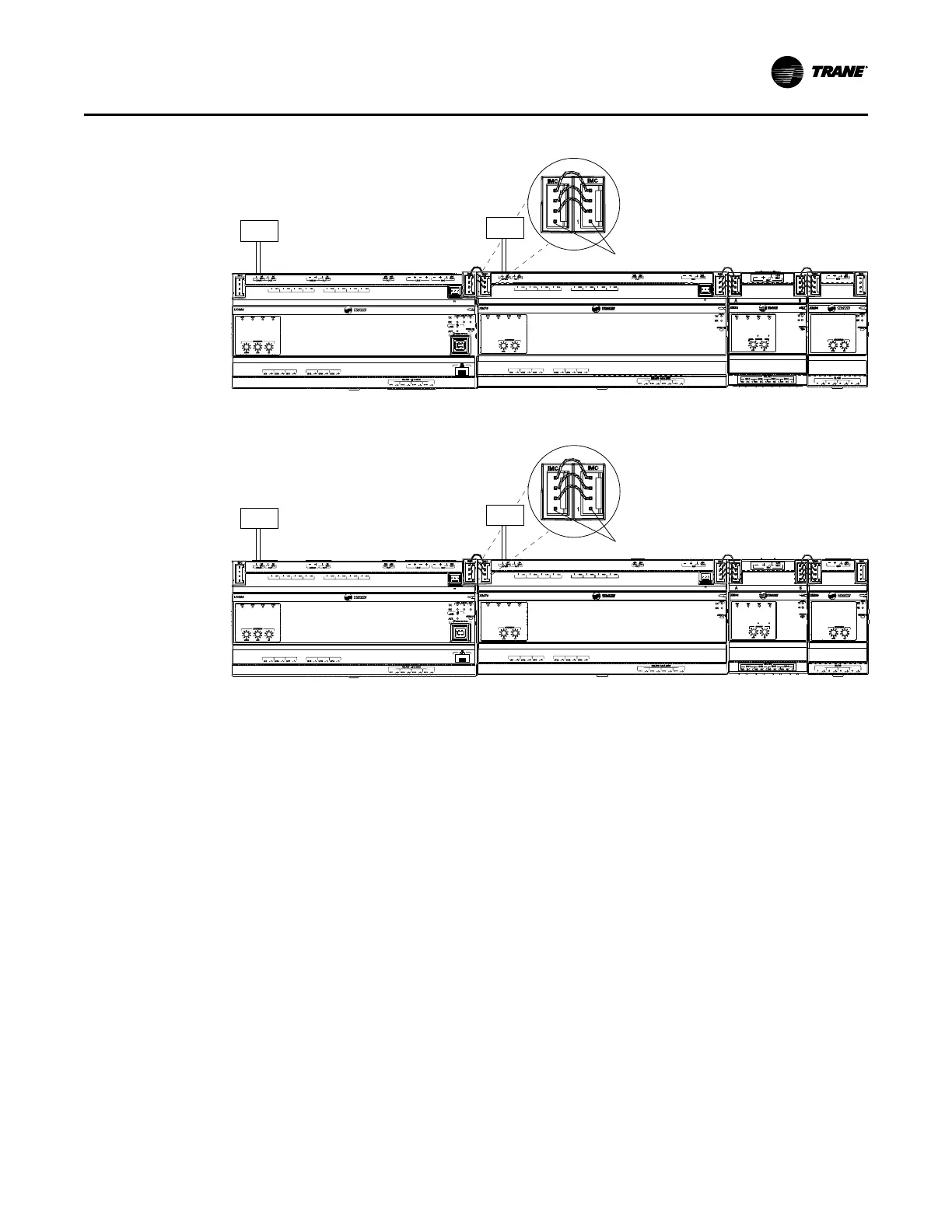
Figure 11. UC600 application with XM70/90, XM32, and XM30 modules
A
O
6
UI
14
A
O
5
UI
13
A
O
4
UI
12
A
O
3
UI
11
A
O
2
UI
10
A
O
1
UI
9
B
O
4
B
O
3
B
O
2
B
O
1
RELAYS 0.5 A MAX
IM
C
1
IM
C
P
1
UI
8
UI
7
UI
6
UI
5
UI
4
UI
3
UI
2
UI
1
IMC
+
24
VDC
OUT
+
24
VDC
+
24
VDC
OUT
24
VAC
XFMR
24
VAC
SERVI
C
E
IM
C
RX
TX
XM
70
ADDRESS
0
1
2
3
4
5
6
7
8
9
x1
0
1
2
3
4
5
6
7
8
9
x10
B
O
4
B
O
3
B
O
2
B
O
1
IM
C
IM
C
TRANE
XM3 2
BO1 BO2 BO3 BO4
ADDRESS
x10 x1
1
2
3
4
5
6
7
8
9
0
1
2
3
4
5
6
7
8
9
0
IMC
SERVICE
RX
TX
RELAYS
BO1 BO2
BO3 BO4
NO NC C NO NC C NO NC C NO NC C
1
A B
IMC
+24
VDC
ADDRESS
0
1
2
3
4
5
6
7
8
9
x1
0
1
2
3
4
5
6
7
8
9
x10
4321
UI / AO
IM
C
1
IM
C
IMC
+
24
VD
C
SERVI
C
E
IM
C
RX
TX
XM
30
ADDRESS
0
1
2
3
4
5
6
7
8
9
x1
0
1
2
3
4
5
6
7
8
9
x10
4321
UI / AO
IM
C
1
IM
C
IMC
+
24
VD
C
SERVI
C
E
IM
C
RX
TX
XM
30
IM
C
IM
C
Red wire
removed
24 Vac
XM70
XM32 XM30
A
O
6
UI
14
A
O
5
UI
13
A
O
4
UI
12
A
O
3
UI
11
A
O
2
UI
10
A
O
1
UI
9
B
O
4
B
O
3
B
O
2
B
O
1
RELAYS
0
.
5
A MAX
1
IM
C
P
1
UI
8
UI
7
UI
6
UI
5
UI
4
UI
3
UI
2
UI
1
IMC
+
24
VDC
LINKOUT
+
24
VDC
+
24
VDC
OUT
24
VAC
MBUS
OUT
24
VAC
XFMR
24
VAC
SERVICE TOOL
SERVI
C
E
LINK
ACT
IM
C
MBUSLINK
RX
TX
U
C
600
ADDRESS
0
1
2
3
4
5
6
7
8
9
x1
0
1
2
3
4
5
6
7
8
9
x10
0
1
2
3
4
5
6
7
8
9
x100
B
O
4
B
O
3
B
O
2
B
O
1
UC600 controller
24 Vac
Important: Do not connect 24 Vdc power between
the XM30 expansion module and the XM70
A
O
6
UI
14
A
O
5
UI
13
A
O
4
UI
12
A
O
3
UI
11
A
O
2
UI
10
A
O
1
UI
9
B
O
4
B
O
3
B
O
2
B
O
1
RELAYS 0.5 A MAX
IM
C
1
IM
C
P
1
UI
8
UI
7
UI
6
UI
5
UI
4
UI
3
UI
2
UI
1
IMC
+
24
VDC
OUT
+
24
VDC
+
24
VDC
OUT
24
VAC
XFMR
24
VAC
SERVI
C
E
IM
C
RX
TX
XM
70
ADDRESS
0
1
2
3
4
5
6
7
8
9
x1
0
1
2
3
4
5
6
7
8
9
x10
B
O
4
B
O
3
B
O
2
B
O
1
IM
C
IM
C
TRANE
XM3 2
BO1 BO2 BO3 BO4
ADDRESS
x10 x1
1
2
3
4
5
6
7
8
9
0
1
2
3
4
5
6
7
8
9
0
IMC
SERVICE
RX
TX
RELAYS
BO1 BO2
BO3 BO4
NO NC C NO NC C NO NC C NO NC C
1
A B
IMC
+24
VDC
ADDRESS
0
1
2
3
4
5
6
7
8
9
x1
0
1
2
3
4
5
6
7
8
9
x10
4321
UI / AO
IM
C
1
IM
C
IMC
+
24
VD
C
SERVI
C
E
IM
C
RX
TX
XM
30
ADDRESS
0
1
2
3
4
5
6
7
8
9
x1
0
1
2
3
4
5
6
7
8
9
x10
4321
UI / AO
IM
C
1
IM
C
IMC
+
24
VD
C
SERVI
C
E
IM
C
RX
TX
XM
30
IM
C
IM
C
Red wire
removed
24 Vac
XM70/XM90
XM32 XM30
A
O
6
UI
14
A
O
5
UI
13
A
O
4
UI
12
A
O
3
UI
11
A
O
2
UI
10
A
O
1
UI
9
B
O
4
B
O
3
B
O
2
B
O
1
RELAYS
0
.
5
A MAX
1
IM
C
P
1
UI
8
UI
7
UI
6
UI
5
UI
4
UI
3
UI
2
UI
1
IMC
+
24
VDC
LINKOUT
+
24
VDC
+
24
VDC
OUT
24
VAC
MBUS
OUT
24
VAC
XFMR
24
VAC
SERVICE TOOL
SERVI
C
E
LINK
ACT
IM
C
MBUSLINK
RX
TX
U
C
600
ADDRESS
0
1
2
3
4
5
6
7
8
9
x1
0
1
2
3
4
5
6
7
8
9
x10
0
1
2
3
4
5
6
7
8
9
x100
B
O
4
B
O
3
B
O
2
B
O
1
UC600 controller
24 Vac
Important: Do not connect 24 Vdc power between
the XM30 expansion module and the XM70/XM90
Remote Mounting
Expansion modules can be mounted remotely by extending the communication and power
wiring from the IMC terminals.
Observe the following when mounting remotely:
• Maximum length of communication wiring cannot exceed 656 ft. (200 m).
NNoottee:: All modules must be wired using a daisy-chain configuration. See BACnet Wiring Best
Practices, (BAS-SVX51) for more information.
• Twisted pair 18 gauge wiring is required for IMC communication.
• A maximum of 2 expansion modules can be powered from a UC400/UC600.
• The Tracer UC400/UC600 can power up to two XM30/32 modules without requiring the
addition of a PM014 Power Supply Module.
Figure 12, p. 20 illustrates a basic example of remote mounting where expansion modules are
locally powered (power is supplied off of a UC400 or UC600). A maximum of two expansion
modules can be powered locally.
Additional expansion modules require the use of a PM014 power supply module.
IInnssttaalllliinngg tthhee TTrraacceerr EExxppaannssiioonn MMoodduulleess

 Loading...