22
BAS-SVX46E-EN
A separate transformer is recommended for each controller. The line input to the transformer
must be equipped with a circuit breaker sized to manage the maximum transformer line current.
If a single transformer is shared by multiple XM70/XM90/UC600 devices:
• The transformer must have sufficient capacity.
• Polarity must be maintained for every XM70/XM90/UC600 device powered by the
transformer.
IImmppoorrttaanntt:: If polarity is inadvertently reversed between controllers that are powered by the
same transformer, a difference of 24 Vac will occur between the grounds of each
controller. The following symptoms could result:
• Partial or full loss of communication on the entire BACnet MS/TP link
• Improper function of XM70/90 expansion module outputs
• Damage to the transformer or a blown transformer fuse
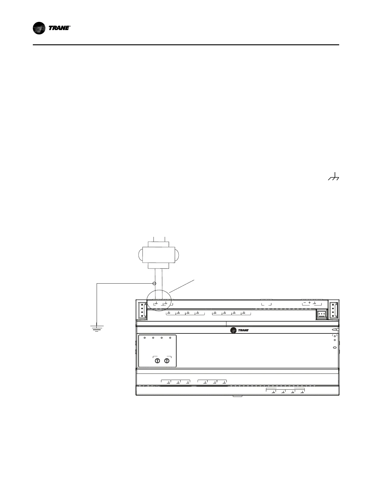
Wiring AC Power to the XM70/90
1. Disconnect all power including remote connections.
2. Connect one secondary wire from the 24 VAC transformer to the chassis ground terminal
3. Connect the other secondary wire to the 24 Vac terminal.
NNoottee:: A pigtail connection is necessary between the earth ground and chassis ground if the
device is not earth-grounded through one leg of the transformer wiring. The XM70/90
expansion module is not earth-grounded through the enclosure.
NNoottee:: The XM70 is shown in the following figure. The XM90 is similar.
Figure 14. Wiring AC power
A
O
6
UI
14
A
O
5
UI
13
A
O
4
UI
12
A
O
3
UI
11
A
O
2
UI
10
A
O
1
UI
9
B
O
4
B
O
3
B
O
2
B
O
1
RELAYS 0.5 A MAX
IM
C
1
IM
C
P
1
UI
8
UI
7
UI
6
UI
5
UI
4
UI
3
UI
2
UI
1
IMC
+
24
VDC
OUT
+
24
VDC
+
24
VDC
OUT
24
VAC
XFMR
24
VAC
SERVI
C
E
IM
C
RX
TX
XM
70
ADDRESS
0
1
2
3
4
5
6
7
8
9
x1
0
1
2
3
4
5
6
7
8
9
x10
B
O
4
B
O
3
B
O
2
B
O
1
Connect secondary transformer
wires here
24 Vac
transformer
Configuring the Expansion Modules
Ensure that the following tasks have been completed before applying power to the expansion
modules:
• Carefully review all IMC communication and power wire guidelines as described in “IMC
Communication and Power Wiring,” p. 14.
IInnssttaalllliinngg tthhee TTrraacceerr EExxppaannssiioonn MMoodduulleess

 Loading...