BAS-SVX10C-EN 33
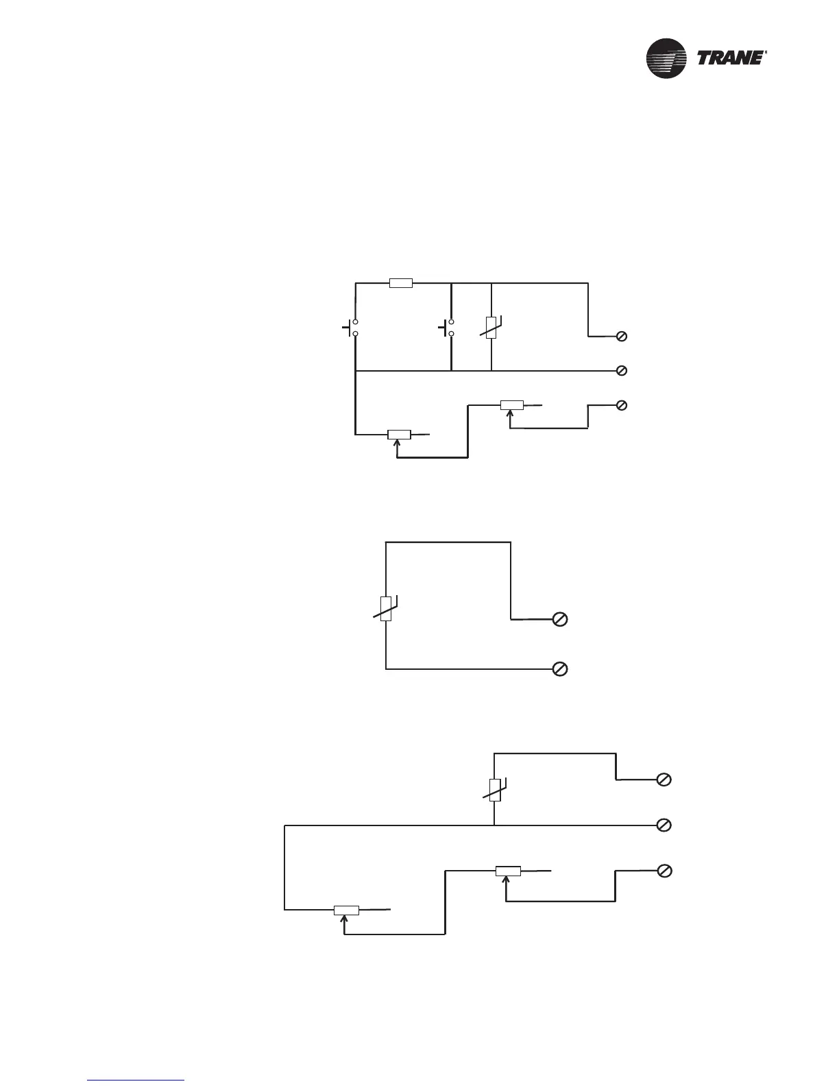
Wiring Diagrams
Each wiring diagram is identified by sensor part number (see “Part Numbers,” p. 6 for reference.)
For wiring information for the display sensor, see Figure 1, p. 10.
Timed
override
Unoccupied
(Cancel) SW2
R1, 1.5 kΩ
Timed
override
Occupied
(On) SW1
RT1
thermistor,
10 k at 25°CΩ
Setpoint
Pot 1, 1 k
potentiometer
Ω
Dwg. source: 3270 3435 B
Zone temperature
Signal common
Setpoint
1
2
3
Calibration potentiometer
Pot 2 (see )Note
NOTE: POT 1 and POT2 are factory calibrated.
Field adjustment voids warranty.
Zone temperature
Signal common
1
2
RT1 thermistor,
10 k at 25°CΩ
Dwg source: 3270 3436
Zone temperature
Signal common
1
2
RT1 thermistor,
10 k at 25°CΩ
Setpoint
3
Setpoint
Pot 1, 1 k
potentiometer
Ω
Calibration potentiometer
Pot 2 (see )Note
Note: Pot 1 and Pot 2 are factory
calibrated. Field adjustment voids
warranty.
Dwg source: 3270 3437
X1351152701
X1351152801
X1351152901

 Loading...