BAS-SVX40A-EN 11
WCI Addressing
Setting Wireless Zone Sensor Receiver Addressing
A WCI that is installed on a unit controller as a wireless communication interface can also function
as a zone sensor receiver. To set up this function, follow this procedure:
WARNING
Hazardous voltage!
Disconnect all electric power, including remote disconnects before servicing. Follow proper
lockout/tagout procedures to ensure that power cannot be inadvertently energized. Failure to
disconnect power before servicing could result in death or serious injury.
1. Make sure that AC power is disconnected from the unit controller that the WCI is installed on.
2. Choose unit controller and wireless zone sensor addresses so that no two wireless zone sensors
sharing the same address are within radio range of each other. (Addresses above 127 may be
used for Wireless Comm systems; see Wireless Comm Network Design Best Practices Guide
(BAS-SVX55) for more information.)
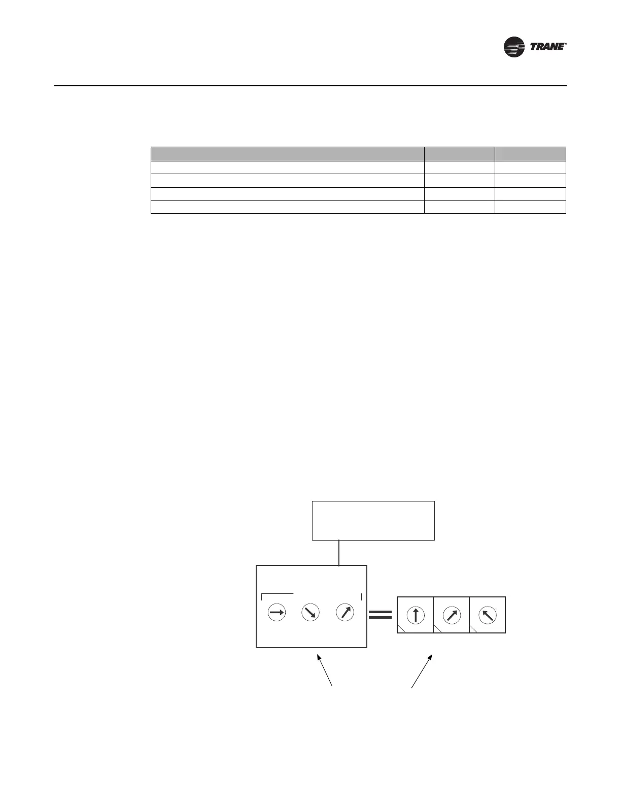
3. Set the address on the wireless zone sensor to match the rotary address setting on the unit
controller (see
Figure 2).
Note: The numbers on the WCI rotary address switches are oriented differently from those on
the unit controllers, as the illustration indicates.
Figure 2. Wireless zone sensor addressing
Table 1. Address settings
Function/Purpose GRP NET
Trane BACnet communication and receiver for sensor 0–8 1–8
Receiver for sensor only 1–9 0
Return to default configuration 0 0
Future use 91–8
1
2
2
3
4
5
6
7
8
9
0
1
3
4
5
6
7
1
2
3
4
5
6
7
8
9
0
8
9
0
UC
Wireless zone
sensor
Match to UC
1
2
3
5
6
7
8
9
0
1
2
3
4
5
6
7
8
9
0
1
2
3
4
5
6
7
8
9
0
ADDRESS
4
WCI as zone
sensor receiver
Be careful to match
addresses rather than the
direction of the arrows.

 Loading...