14 BAS-SVX40A-EN
Mounting and Wiring the WCI
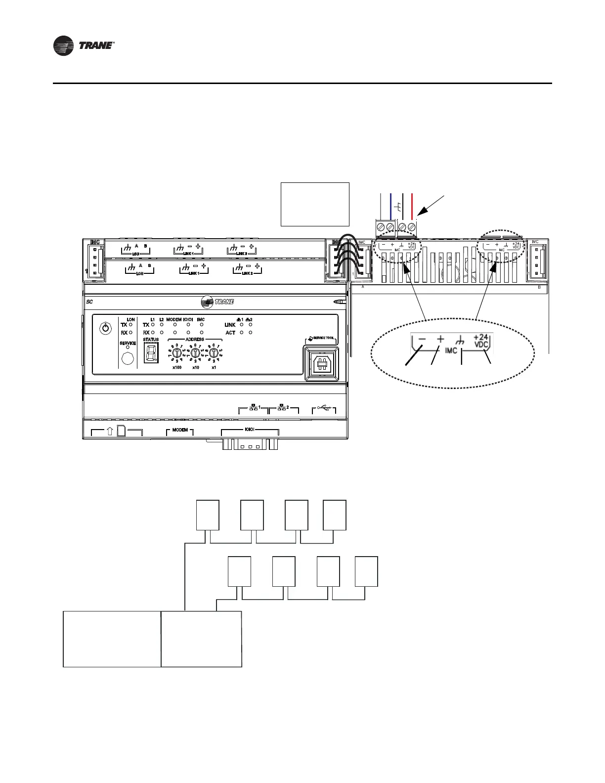
Figure 6. Wiring the WCI to a Tracer SC
Figure 7. Wiring multiple WCIs to a Tracer SC
Tracer SC
PM014
WCI wiring
LINK +
LINK –
+ 24VDC
IMC– IMC+
Grou nd 2 4 Vd c
Gray = LINK -
Blue = LINK +
Black = Ground
Red = 24 Vdc
Connect both 2-connector
screw terminal blocks to
either of the IMC terminals
on the PM014.
WCI WCIWCIWCI
WCI WCIWCIWCI
Tracer SC
PM014
Notes:
• A maximum of eight WCIs can
be daisy-chained to the Tracer
SC.
• Use both IMC terminals on the
PM014 for wiring multiple WCIs
(see the detail in Figure 6).

 Loading...