Troy-Bilt Small Frame Tillers
37
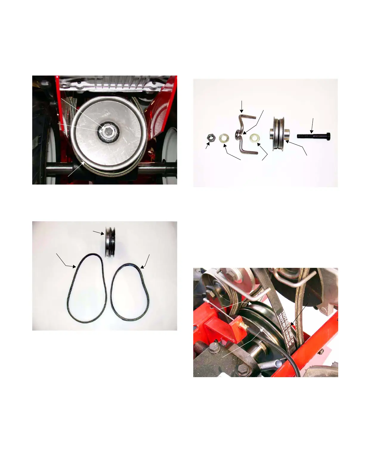
3.8. Remove the hex screw and belleville washer
securing the transmission pulley to the drive
shaft assembly using a 1/2” socket. See Figure
3.8.
3.9. Remove the transmission pulley and drive belts
from the drive shaft assembly. See Figure 3.9.
NOTE: Make certain the front support washer
and square key are in position before installing
the transmission pulley.
3.10. Install a new reverse drive belt in the reverse
order above.
NOTE: Make certain the reverse drive belt is
installed inside-out.
Figure 3.8
Hex Screw
Belleville
Washer
Transmission Pulley
Figure 3.9
Transmission Pulley
Inside-Out
Reverse Drive Belt
Forward Drive Belt
4. REVERSE IDLER PULLEY ASSEMBLY:
4.1. The following picture shows the reverse idler
assembly components in their correct orienta-
tion. See Figure 4.1.
NOTE: The open center of the reverse belt
guide, for the reverse idler, is position down dur-
ing assembly.
5. TRANSMISSION PULLEY:
5.1. The following picture shows the V-pulley section,
and the flat pulley sections of the transmission
pulley. See Figure 5.1.
NOTE: The reverse drive belt runs inside-out on
the transmission pulley.
Figure 4.1
Lock Nut
Flat Washers
Belt Guide
Open Center
Reverse Idler Pulley
Hex Screw
Figure 5.1
Transmission
Pulley
Flat Pulley Half
V-Pulley Half

 Loading...