2–2 AeroTrak™ Remote Airborne Particle Counters
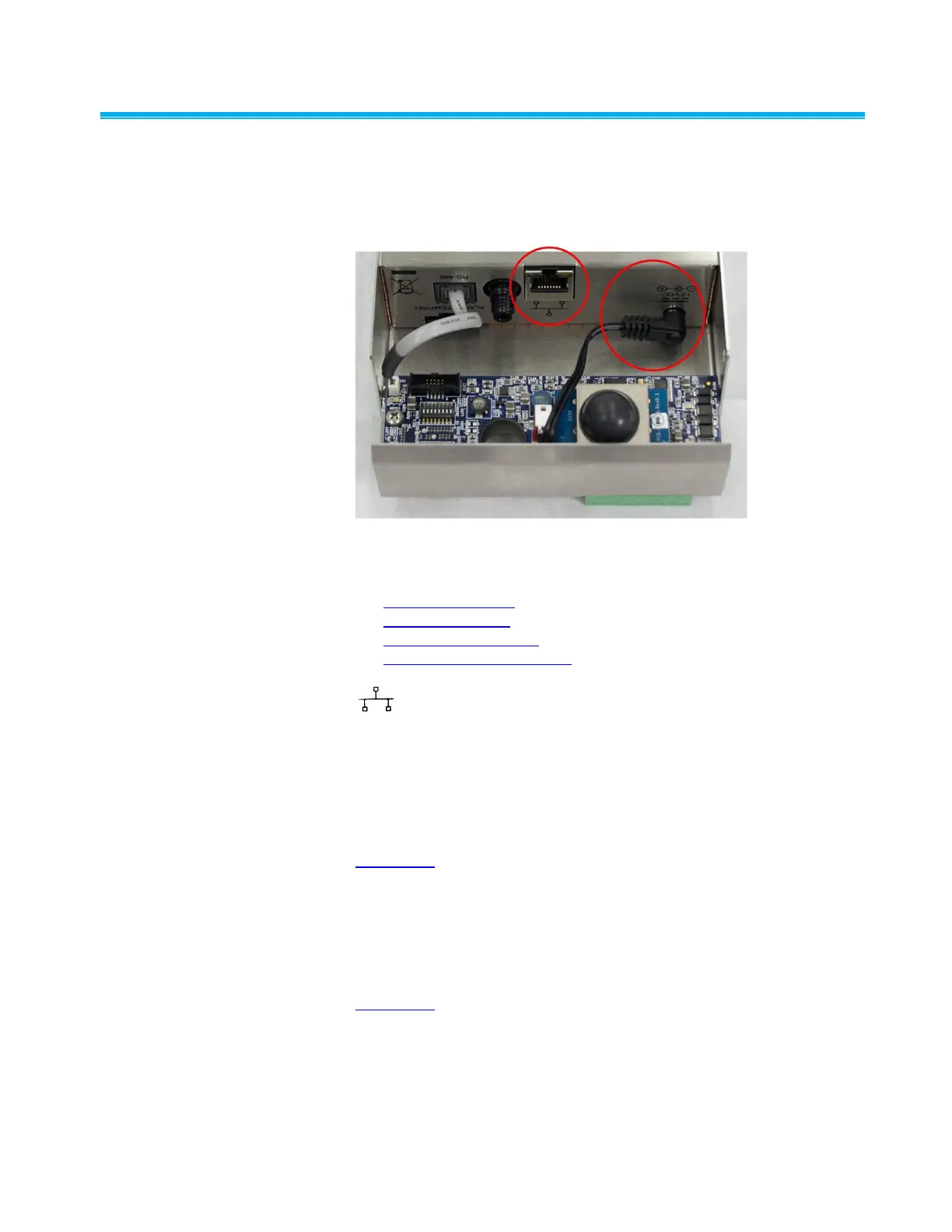
Intern a l Ele c t r ical Connec t i o n s
The AeroTrak
®
Remote Airborne Particle Counter (particle counter)
supports multiple communications and connectivity options. A brief
description of each of the connections is listed below.
Device Connections
Ethernet connector
12 VDC connector
RS-232/485 connector
Alarm, Temp/RH connector
Ethernet Connector
The RJ45 Ethernet connector is the only internal electric connector you
will need to use. It is used only for setting up the sensor configuration.
12 VDC Connector
Power for these AeroTrak Particle Counters comes from the 24 VDC
pinned inputs on the bottom of the product (see wiring diagram in
Appendix A). The internal circuit board converts power from 24 VDC to a
barrel-type 12 VDC power input that is prewired into the unit at that
factory.
RS-232/485 Connector
This connection is used to communicate from the particle counter to the
4-20 mA analog outputs and alarm contacts in the wiring diagram (see
Appendix A). This is prewired at the factory and there is no need to
disconnect this connection.
 Loading...